
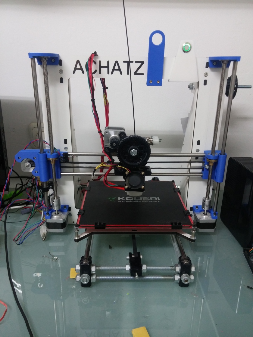
I built my 3D printer more than a year ago and I think it’s time for an upgrade.
This upgrade was long due and delayed because of lack of time (I worked full time in the summer) and the crawling pace in which the local postage service here works, but enough excuses – let the fun begin!


This upgrade will concentrate on the Z axis movement only, and the replacement of the threaded rods with proper lead screws.
Lead Screw? But Why?
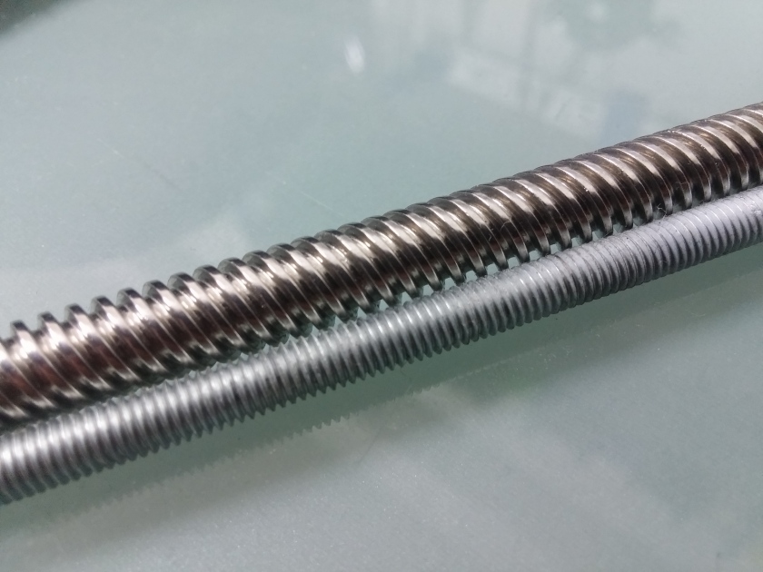
After a year of printing, it can clearly be seen that threaded rods are not meant for this kind of application. The rod itself is not straight (which is not that big of a deal because there are straight rods keeping the movement straight), it squeaks pretty loudly during movement and its threads get full of black goo that consists of dust, oil and metal shavings from the friction with the nut.


A threaded rod is meant to be tightened with a nut and not move, the whole principal of its operation is based on friction – a thing we don’t really want in a moving mechanism.
A lead screw is much more rigid, it’s very hard so it doesn’t bend, it has a very smooth surface and its shape is specifically designed for moving inside a nut.
Made from scratch
I searched for a premade model so I wouldn’t have to model everything from scratch, but with all the different variations and sub-models of the Prusa i3, I couldn’t find one that I was sure would fit without further alterations. Eventually, I decided to design them myself and share for everyone with a similar printer to mine.
I had some big plans and special designs for this project, but It would take a lot of time and I couldn’t stand the threaded rods any more, so I decided to take the current design and improve on it. After the printer is functional with the threaded rods installed, I could take my time and experiment.
This project took two days total over the weekend, including modeling, printing and installing.


To keep the nut in place, I embedded M3 knurl nuts in holes in the plastic about 0.5 mm smaller in diameter than the outside of the nuts. The nuts are inserted by heating them with a soldering iron and pushing them in. A screw helps keep the nut straight while it’s inserted.
The linear bearings are held in place by the plastic itself.


At first, I thought I could get away with replacing only the X axis mounts, but I didn’t account for the lead screw’s center that had to move to make room for the big nut. eventually (after disassembling the printer, swapping the mounts, reassembling and realizing the mistake) I remodeled the mounts, printed them again and reassembled everything.


The old top bracket only supported the straight rod, the threaded rod’s top was floating, which didn’t help with it not being straight.
I improved on the design by including support for the new lead screw, which barely needs it thanks to it’s rigidity.
Instead of letting the lead screw move inside a hole in the plastic, I included bearings that hold the lead screw securely in place while letting it rotate freely.


The bottom brackets are basically the same, I just had to move the straight rod’s hole further out to follow the center dictated by the X axis carriage and the bigger lead screw nut.


All parts were printed in blue PLA @ 0.2 mm layer height and 200 degrees C with no support and no heated bed.
All models are available for Free download on Thinginverse.
The lead screw and threaded rod have different thread counts (the amount of turns per length unit) so the steps per millimeter value for the Z axis needs to be changed in the firmware. This is easily done by simply moving the Z axis 100 mm (direction doesn’t matter), measuring the actual movement and multiplying the current steps per millimeter value by the actual movement measured divided by 100 (watch your units). Repeat this process a few times, each time gets you closer until you reach the accuracy wanted.
Note that the error will be more apparent with longer movements. If you move your axis 1 mm and measure you might not see the error. A 1% error would translate to 0.01 mm with a 1 mm movement (which is something my analog caliper can’t measure), but with a 100 mm movement it would be much clearer at 1 mm.
That’s it. All done. No more squeaking Z axis and wobbly rods. I don’t expect a real improvement in printing quality, although that would be nice, but an improvement in the printing experience.
Final Thoughts
I’ve had some comments about losing resolution with lead screws because of the lower thread count, so lets see if that’s true (spoiler – it’s not):
The threaded rod I had measured at about 1 mm per turn (if I turn it inside a nut once, it will move 1 mm through the nut) and the lead screw measures at around 7.5 mm.
This means that my lead screw is 7.5 times faster than my threaded rod. If I want them to move the same distance, I need to turn the lead screw 7.5 times less than the threaded rod.
If I had a continuously rotating motor, I could, theoretically, have the same resolution (infinite) but the motors used in my printer are stepper motors, these motors move in steps and not continuously. My motors take 200 steps to make a full turn, this is the maximum resolution we can reach (well, there’s microstepping but the idea is the same, there still is a step to be made that determines the maximum resolution and amount of error to be expected).
With 200 steps per turn and 1 mm per turn, we get 200 steps per millimeter. That’s 0.005 mm per step. That’s the smallest increment in length we can make without microstepping.
At 7.5 mm per turn we get 0.0375 mm per step. While this is a larger number, the smallest increment you would expect to make while printing is still even larger. So what does this mean?
This means that the Maximum resolution your axle can reach will go down, but because the actual maximum resolution a 3D printer can reach is even lower, this doesn’t matter.
The maximum resolution I reached with my printer is 0.1 mm layer height and I don’t print at that resolution often. Even if I try to reach 0.05 mm, the lead screw would still be enough. Moreover, my firmware has microstepping enabled so the maximum resolution is much higher (microstepping can go down to 1/32 or even 1/64 of a step) and if I really want to go crazy, I could get geared motors to reduce the ratio to 1:14, 1:30 or even slower.

“The old top bracket only supported the straight rod, the threaded rod’s top was floating, which didn’t help with it not being straight.”
The top of the threaded rod is unconstrained by design, that way any wobble ends up at the top rather than in the middle (where you don’t want it). The jury is out on whether you should do this with lead screws. I would try it with and without the top constraints and see which is better.
See also https://www.reddit.com/r/Reprap/comments/2tv2qq/should_i_stabilize_my_threaded_rods/
LikeLike
Keeping the top unconstrained may address one issue, but it creates another.
The threaded rods are not very hard, therefore their resonance frequency is not that high, in fact, when I move the Z axis, the threaded rods start ringing loudly, this is due to the vibrations being amplified by the rod itself. This might not be physically apparent on the printed models because there is very little Z axis travel during prints and usually there’s no extrusion during Z axis travel (accept for vase mode).
Because the threaded rods are not constrained, they warp even more over time, introducing more friction in movement, grinding the rod and nut, filling the threads with metal powder, causing more vibrations.
The lead screws are very hard, heavy, straight and smooth. This means that their resonance frequency is much higher (higher than the step frequency of the motors), they don’t warp and they don’t grind so there’s less vibration to begin with.
Moreover, with the lead screws the motors rotate much slower (due to the lower thread count), thus introducing a lower vibration frequency that’s further away from the lead screw’s resonance frequency.
It all boils down to the threaded rod just being unfit for the job.
I might try to compare constrained lead screws vs. unconstrained, but I don’t expect a big difference. The lead screws don’t wobble and constraining the top helps the flexible coupling at the bottom dampen the minor vibrations that might exist.
In general, most vibrations that are apparent in the printed model are caused by hard acceleration of the X and Y axis with a heavy X carriage and bed. This is due to the elasticity of the belts and the tolerances in all parts. This will be addressed in future projects.
LikeLike
2 Questions:
1) Where did you bought these constrainers for the threads?
2) Do you have photos of after/before print quality?
I bought 2 leadscrews rods (8 mm per turn now vs 2 of the old threaded rods) for my hictop prusa but while I was designing the new parts to replace the original nut, I saw this in Hackaday and this probably saves me quite the testing!
LikeLiked by 1 person
1) I’m not sure to which part you are referring. The lead screws are held on top with bearings, this type of bearing has a small screw to secure it to the lead screw (or whatever shaft you use), I bought them off eBay.
The carriages move along the lead screw with nuts that match the lead screws, they come with the lead screws themselves and I bought them off eBay.
2) I don’t have photos and I don’t expect a very noticeable improvement in print quality with this upgrade alone. There are a lot of other elements that influence the print quality, which I intend to improve in the near future and definitely have some before/after comparison. As I mentioned, this is mostly supposed to address some issues that appear over time and to reduce the degradation and need for maintenance of the printer.
LikeLike
Oh another question:
How did you prevented leaving dents in the lead screw when tightening the grub screws in the spring coupler?
LikeLike
I didn’t.
The lead screws are very hard, the don’t dent easily. They might scratch but that part stays inside the coupling so the nut doesn’t even get there. Why does this matter to you?
LikeLike
Well, it does matter because I dented the current threaded screw and it was a pain to remove them. So I would like to leave them perfect.
I ordered some leadscrews but I think is weird how they advance 8 mm per turn vs the crappy threaded rods that advanced 2 mm per turn. I hope this does not affect the Z axis resolution.
Can you share the link for these bearings with grub screws?
Thanks a lot for answering.
LikeLike
Interesting.. mine only have some surface scratches when I try to abuse them. Even tried to do some damage with a pair of pliers but couldn’t dent it in a way that would cause it to get stuck.
Are you sure they’re stainless steel? Maybe you accidentally hit the edge of the thread, which is weaker, thus causing more damage.
The listing for the bearings I ordered is not available anymore, but these seem to be the same:
http://www.ebay.com/itm/2Pcs-Zinc-Alloy-Diameter-8mm-Bore-Ball-Bearing-Pillow-Block-Mounted-Support-KP08-/311473590411?hash=item488545d08b:g:HG0AAOSwhcJWMDYr
LikeLike
I wonder if you can do without the guide rods entirely when using threaded rod. That would be a nice simplification of the design, IMHO.
LikeLiked by 1 person
The motor drives the lead screw through a flexible metal coupling. If the motor had a lead screw for a shaft so it’s perfectly aligned and very rigid (this actually exists), this might have been possible, but because they are coupled with a flexible coupling and the lead screw is fixed on top, the lead screw could move like a spring loaded pendulum and generate even more vibrations in X and Y axes even when the Z axis is not moving.
The straight rod helps keep the lead screw aligned with the carriage and the Z axis as the carriage is in contact with the lead screw at a single point – the nut (which has some tolerance). If two nuts with some distance between them have been used, the carriage would have been parallel to the Z axis with no extra help (to a certain degree).
This might be possible, but requires some more design changes and special parts.
An interesting idea though, thanks.
LikeLike
Great job! We hope http://www.Libre3D.com can have a talented person like yourself to post for the community 🙂
LikeLike
Nice work!
I have made the same upgrade on my printer (not with your designed parts) but the Z axis don’t move any more if all the screws are tighten on the lead screw nuts.
Have you intentionally loosen the screws on the right X axis carriage like it seems to be on the picture to avoid this problem?
LikeLike
No, all the screws are tightly fastened.
There’s a small gap between the nut and the right X axis carriage because I didn’t account for the rim of the nut when I designed the part. After printing one part and noticing the issue, I included a recess for the rim in the model of the other part.
I intended to print the right X axis carriage again with the recess included, but I printed a lot that day and worked a lot on this so I was tired, or in other words – I was lazy.
The phenomenon you describe might be caused by the parts not being perfectly aligned.
When I designed the models I made sure all the holes are perfectly aligned. I did this by stripping one model from everything but the holes and constructing the new model on top of them. That way I eliminate the chance for mistakes.
By leaving some screws unfastened, you allow a larger tolerance and and the rod can rotate freely. However, this is now ideal, you might experience some wobble and the screws might even fall off.
LikeLike
Hello again!
I finished all the modifications to my prusa following your example (excepting the upper rod ball bearing retainers) but I have a question about the marlin configuration, which value do you use for the steps exactly?
The operation is so smooth now!
LikeLike
Glad it’s working for you. It’s so satisfying seeing someone else finding my creations useful.
I just checked and my Z steps/mm value is 418.95 (I don’t know if the decimal is necessary, I haven’t looked at the code to see it it’s rounded or not, but it can’t hurt. I might check that later just to feed my curiosity)
I suggest you calibrate manually and figure out the values that fit your printer. Theoretically, assuming you’re using 200 steps/revolution motors and the same threads/turn rods, it should be the same value, but calibrating and generating your own values is good practice and is guaranteed to bring good results.
Good Luck!
LikeLike
I believe you miscalculated the resolution you need. If you are printing in 0.1mm layers, and your setup only gives you 0.0375mm steps, you will only be able to set layers of either 0.075mm or 0.1125mm. In order to have more resolution you need to use microstepping or go with a smaller lead distance. I guess 4mm lead is sufficient, since you will be working with multiples of 0.02mm
LikeLike
That is correct. However, I did not miscalculate, just didn’t fully explain.
The RAMPS board features jumpers for microstepping which are set to maximum microstepping by default (the actual ratio depends on the driver you use). it supports up to 1/128th of a step. That takes care of the problem in my case (I believe my drivers use 1/16th microsteps).
The problem is real, without microstepping you need to use layer heights that are multiples of your step size. If I use 0.1mm layer height with the current setup, I would get a 12.5% error accumulating every layer. After 8 layers, I would have missed a layer – that is assuming the firmware just increments by the closest value to 0.1mm.
I peeked at the firmware and if I understand it correctly, the firmware keeps track of the absolute position of the axis (in a floating point variable) and sends the difference needed to reach the desired level height (the Gcode includes the destination height and not the increment). If so, and if we’re not using microstepping, we would not be missing a layer, but having some overlap between layers.
The first layer would be printed at 0.1125mm as it’s closer to 0.1mm than 0.75mm. The second layer would be printed at 0.1875mm, as it’s closer to 0.2mm than 0.225mm. The third layer would be printed at 0.3mm. This cycle would repeat itself every 8 steps, or every 3 layers.
This gives us 12.5% error in the absolute height of the top of the layer, and 25% error in actual layer thickness (the height between tops of two adjacent layers). Of course, the error decreases linearly with increasing layer thickness.
This, combined with microstepping, would result in a maximum overlap of one microstep. While not perfect, this is tolerable for this application.
What replacing the threaded rods did was increase the error by a factor of 7.5.
The issue of misaligned intervals can also be resolved in software – just use 0.1125 as the layer height and you’ll have perfect alignment. I doubt you’ll notice the difference.
As I mentioned, you can also use geared motors to further shrink your full step size and consequently, the error.
I did not think of this when I decided to move to lead screws, I just trusted the firmware to do it for me. It was more of a structural upgrade than a performance one.
While I did not plan to, this comment made me really dig in to the guts of the printer and kind of reverse engineer it. This might help me reach 0.05mm (or 0.04921875 in my case 😉 ).
Thanks.
LikeLike
Hi, have been trying to print , but am having problems.
first up I am using Simplify3D, and it sliced the motor part good but back to front, after mirror it , I could not get it to print properly, it jumped layers after printing up to the first motor holes, not matter what I changed just could not get past that. What slicer program did you use.
LikeLike
I’m also using Simplify3d.
That’s strange, I know of several people who printed it successfully without modification. I’ll check my files again and try to print the part.
LikeLike
Daniel, thanks, I also tried it in Matter control and it still sliced mirrored, so not sure what is wrong.
LikeLike
Forgive this potentially stupid question, but with this upgrade how it the belt tensioned?
LikeLike
Not that stupid of a question, I’m surprised no one has asked this before.
In this version, the belt is tensioned upon installation, much like most of the printers today.
I am, however, working on a version with a tightening mechanism, but it might take some time because I have a lot in my backlog..
Hope it works for you.
LikeLike
https://www.thingiverse.com/thing:10082
LikeLike
Thank you Sir.
Have done the upgrade, and it works a treat, added a belt tightning adjustment, it runs a smooth as silk.
LikeLike
How did you get the bearings out of the mounts, I can’t see how you removed them?
LikeLike
The bearing needs to rotate 90 degrees on its axis inside the frame (the axis that’s perpendicular to the surface on which it’s sitting), this can be done by leveraging with a pen or a rod (some force needed), then it needs to rotate 90 degrees on the other axis to meet the two notches on the one side. the bearing can then slip out through the notches.
good luck!
LikeLiked by 1 person
Thanks mate
Simple when you know how.
LikeLike
I looked around and couldn’t find a bill of materials for this project.
LikeLike
Here you go :
– 300mm long 8mm diameter lead screw. I measured about 1 turn per 1cm length. I don’t know all the specifications for it so I can’t give you a model name.
It came with matching nuts.
Here is a link to a similar one on eBay :
http://www.ebay.com/itm/T8-2-8mm-3D-Printer-Accessories-Lead-Screw-Rod-150-to-600mm-Nut-T8-Stepper-Motor-/351846889722?var=&hash=item51ebb578fa:m:mogd8q0ZqRwLrcTOdrmC_lA
– KP08 bearings. Here’s a link :
http://www.ebay.com/itm/2Pcs-Zinc-Alloy-Diameter-8mm-Bore-Ball-Bearing-Pillow-Block-Mounted-Support-KP08-/311473590411?hash=item488545d08b:g:HG0AAOSwhcJWMDYr&afsrc=1&rmvSB=true
You can read how to separate the bearing from the housing in one of the comments here.
– 5mm to 8mm metal couplings. Link :
http://www.ebay.com/itm/Flexible-Clamp-Jaw-Shaft-Coupling-CNC-Stepper-Motor-Coupler-Router-5×5-8MM-/181904676273?var=&hash=item2a5a5d15b1:m:mNHZ6KYFc9kWbkd37h6vzPw
There are options in that lsitling, verify that you choose 5X8.
GL;HF.
LikeLike
bad, no fine Z screw.
LikeLike
You made some first rate points there. I appeared on the internet for the problem and located most people will go together with with your website.
LikeLike