Rack Cable Management
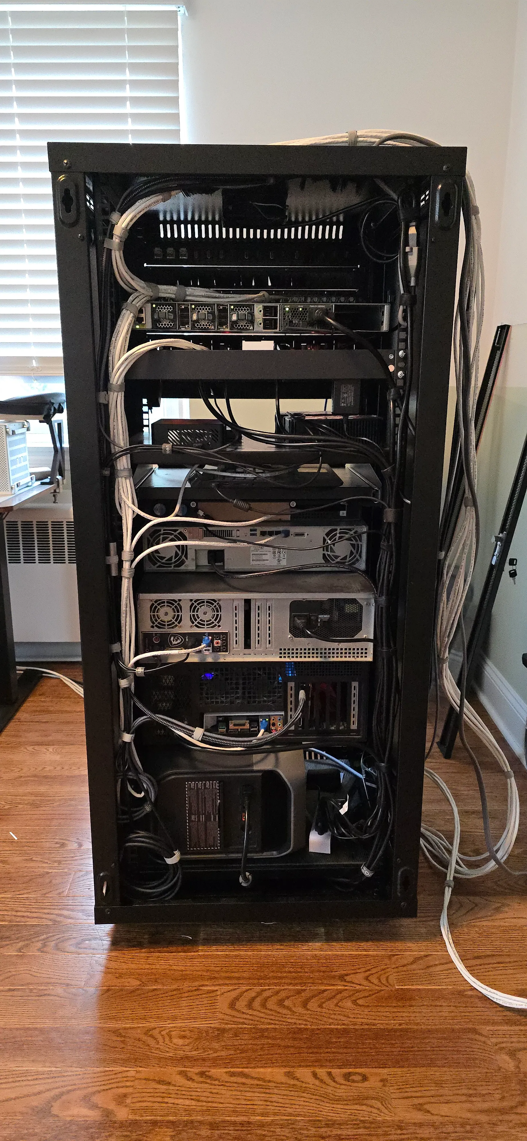
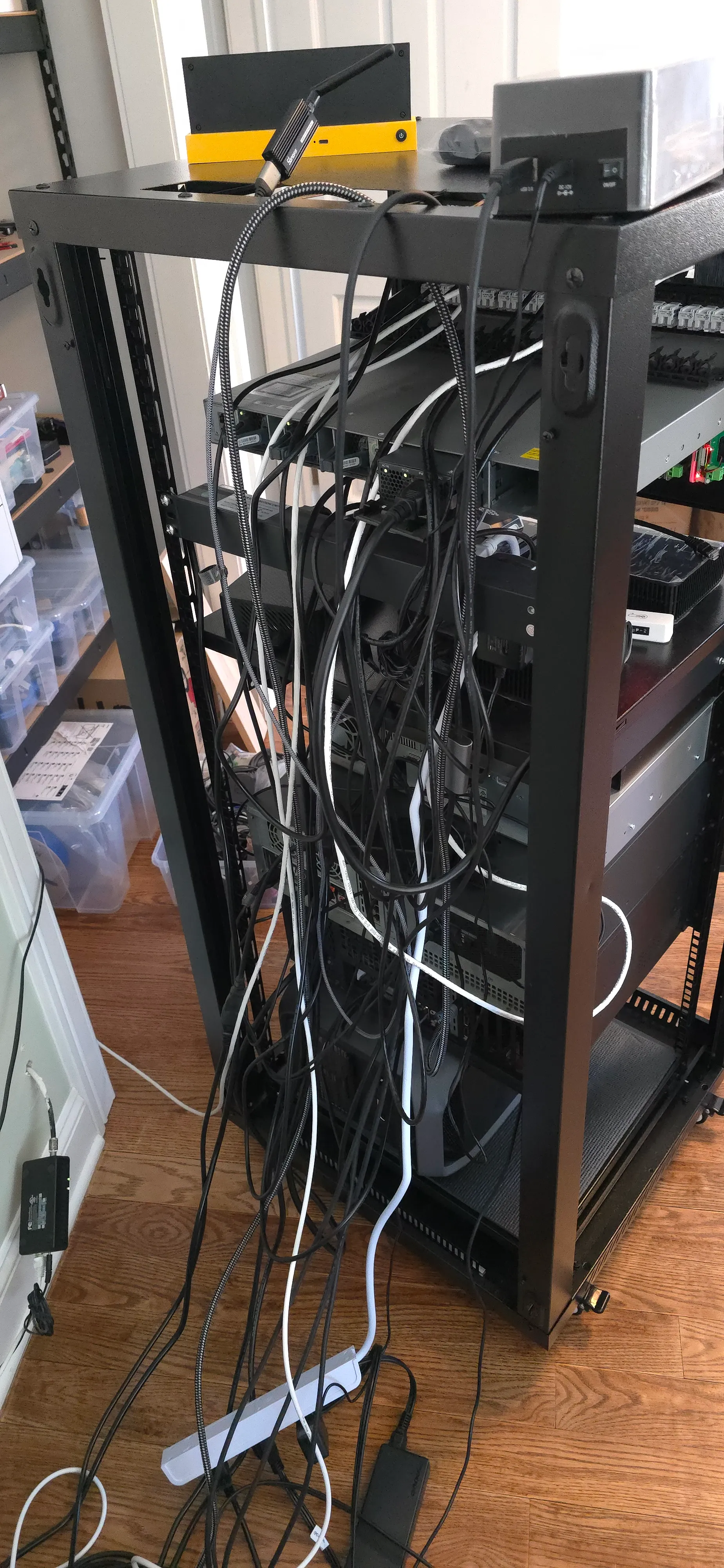
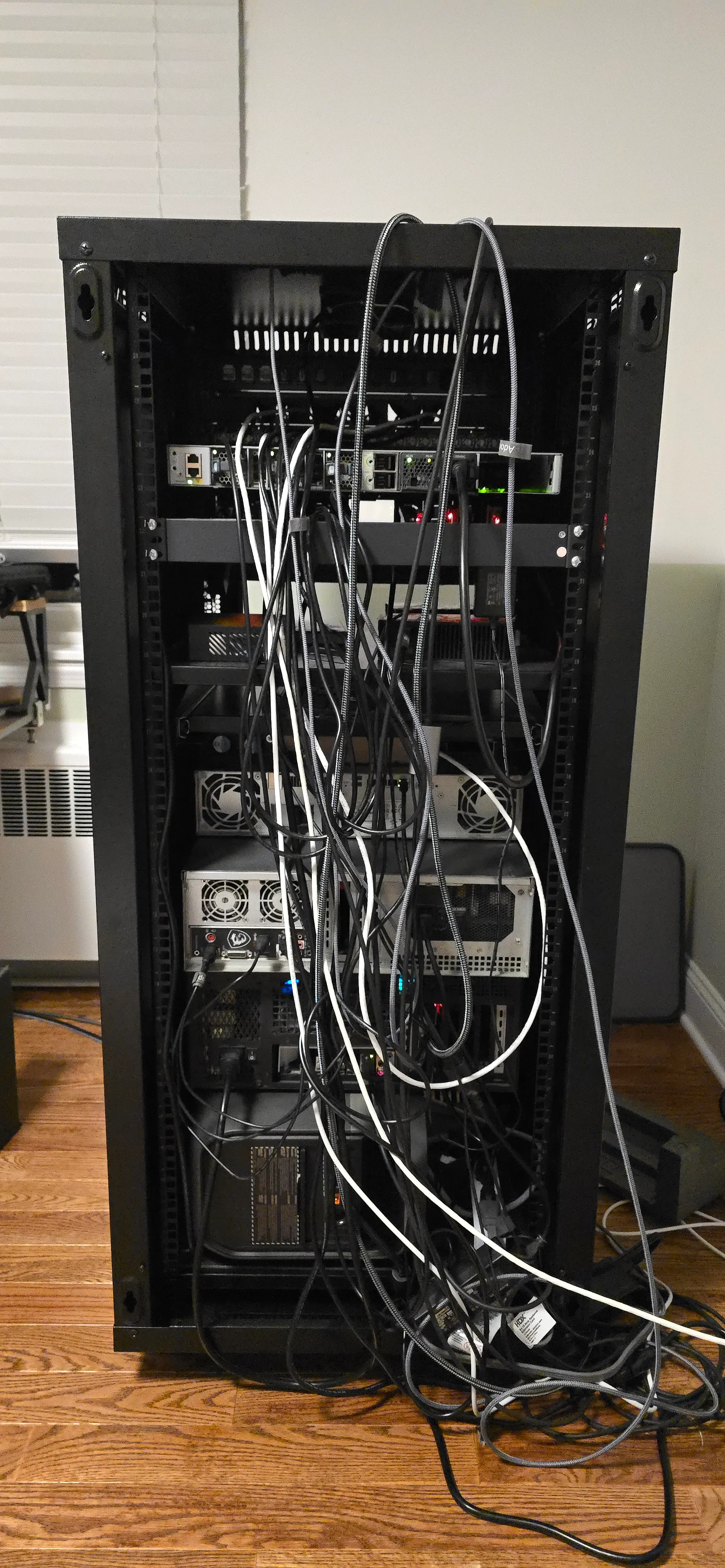
Consolidating all of my equipment into a rack was a game changer in terms of space utilization and order, but cable management was always overlooked. I tried to keep it untangled so I can at least work with it, but it’s time to get rid of the electrical spaghetti and turn the curly afro into nicely combed ponytails.
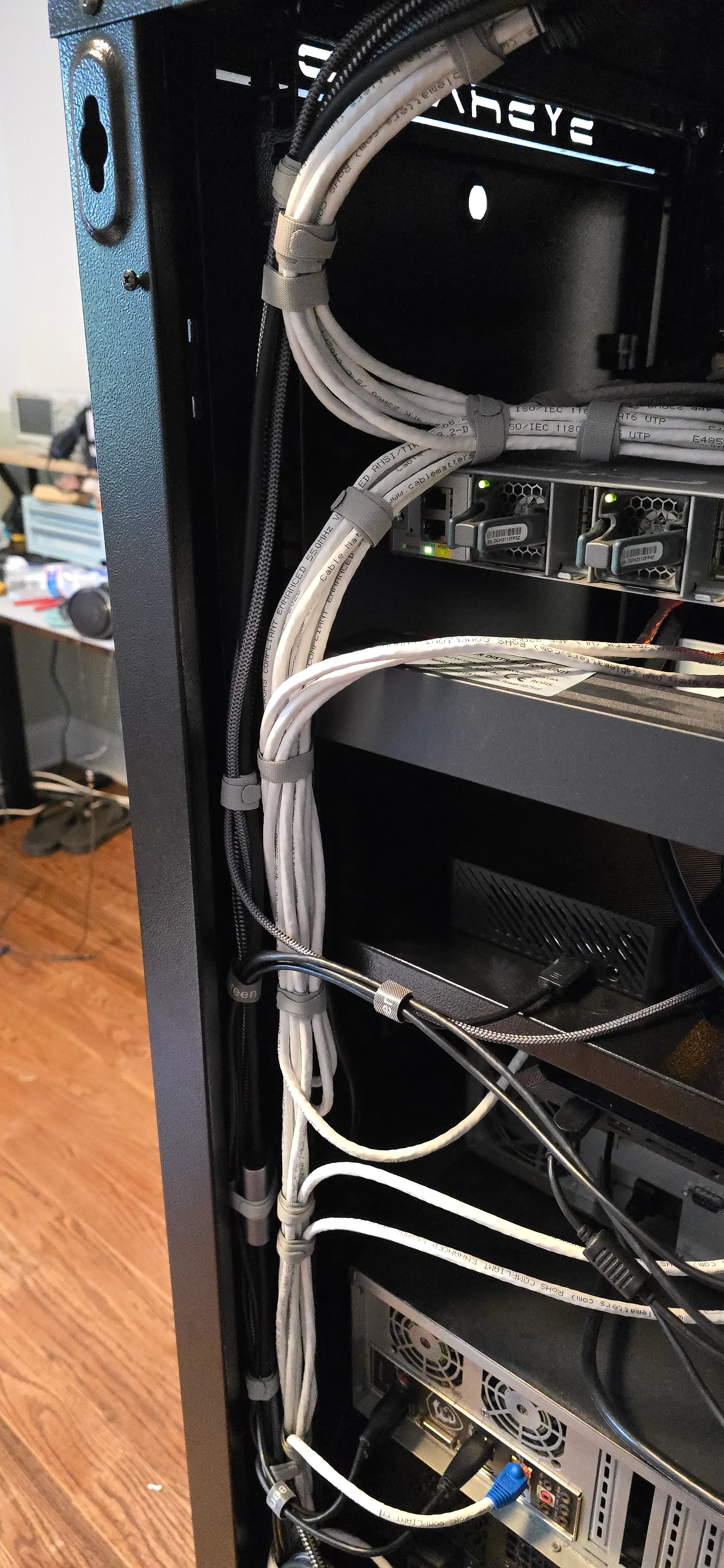
I moved recently and was forced to migrate all of my gear from my old rack into a new one, so at least I have a better starting point for the back of the rack.
All of the cables were freshly hooked up and not part of the nest that was there before, after years of unplugging cables and plugging them back in wherever was convenient and not wherever wouldn’t make knots.
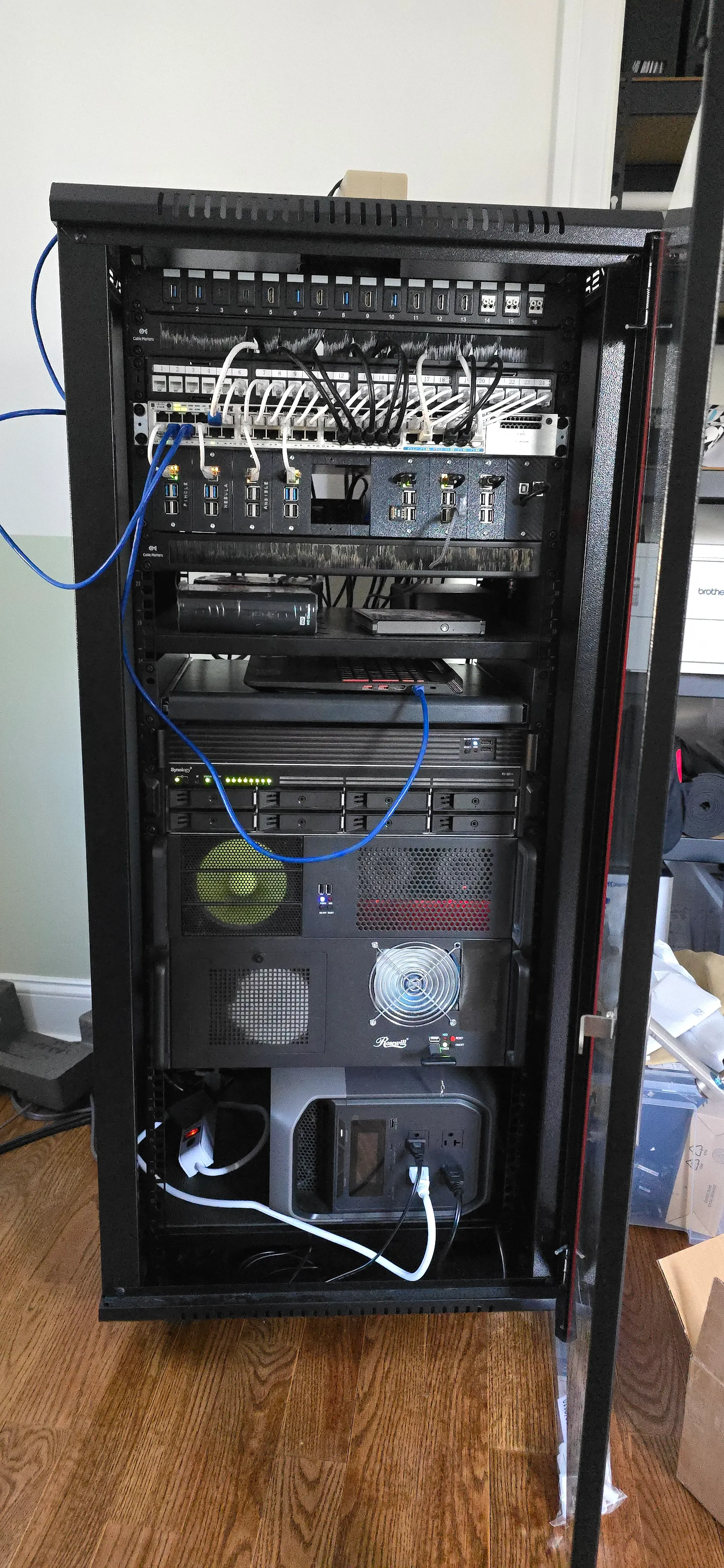
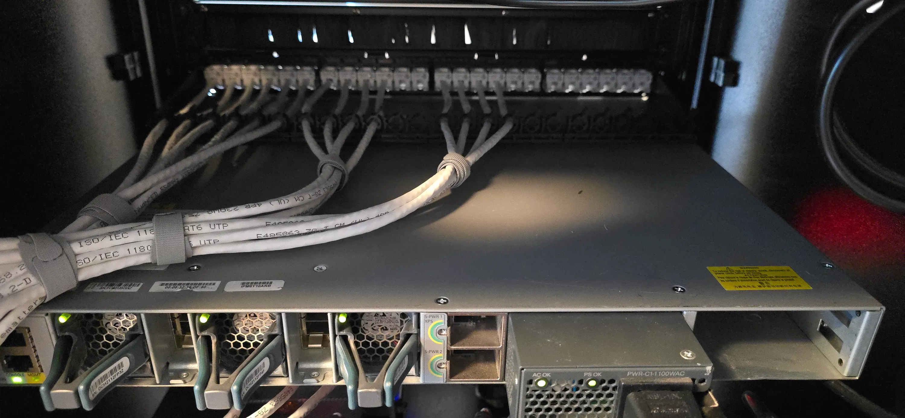
On the other hand, the front of the rack looks a little worse because the patch panel is not connected yet, so all the cables come through a brush panel straight into the switch, with some cables just dangling, coming out of the front of the rack.
The Plan
I will divide the cables into two bundles. A data cables bundle and a power cables bundle. This will make it easier to maintain and upgrade as well as reduce the chance for electromagnetic interference.
The process is going to take multiple days, so to prevent multi-day downtime for my machines, as well as multiple power-off-and-ons, I’ll start with the network cables. They can be unplugged and plugged back in without having too much of an effect on anything (mostly, more on that later).
After that, I’ll tackle other data cables, like USB and video. Some of them can’t just be yanked and need manual treatment at the application level to avoid data loss or hardware failure.
For convenience, these will be bundled together and then attached to the network cables bundle. That way, I could separate them and maintain each of the sub-bundles without affecting the other.
Finally, I’ll manage the power cables. This is tricky since the cables go to multiple places, and because I have a UPS, there’s some power cascading.
This stage needs to be done once and quickly.
Data Bundle
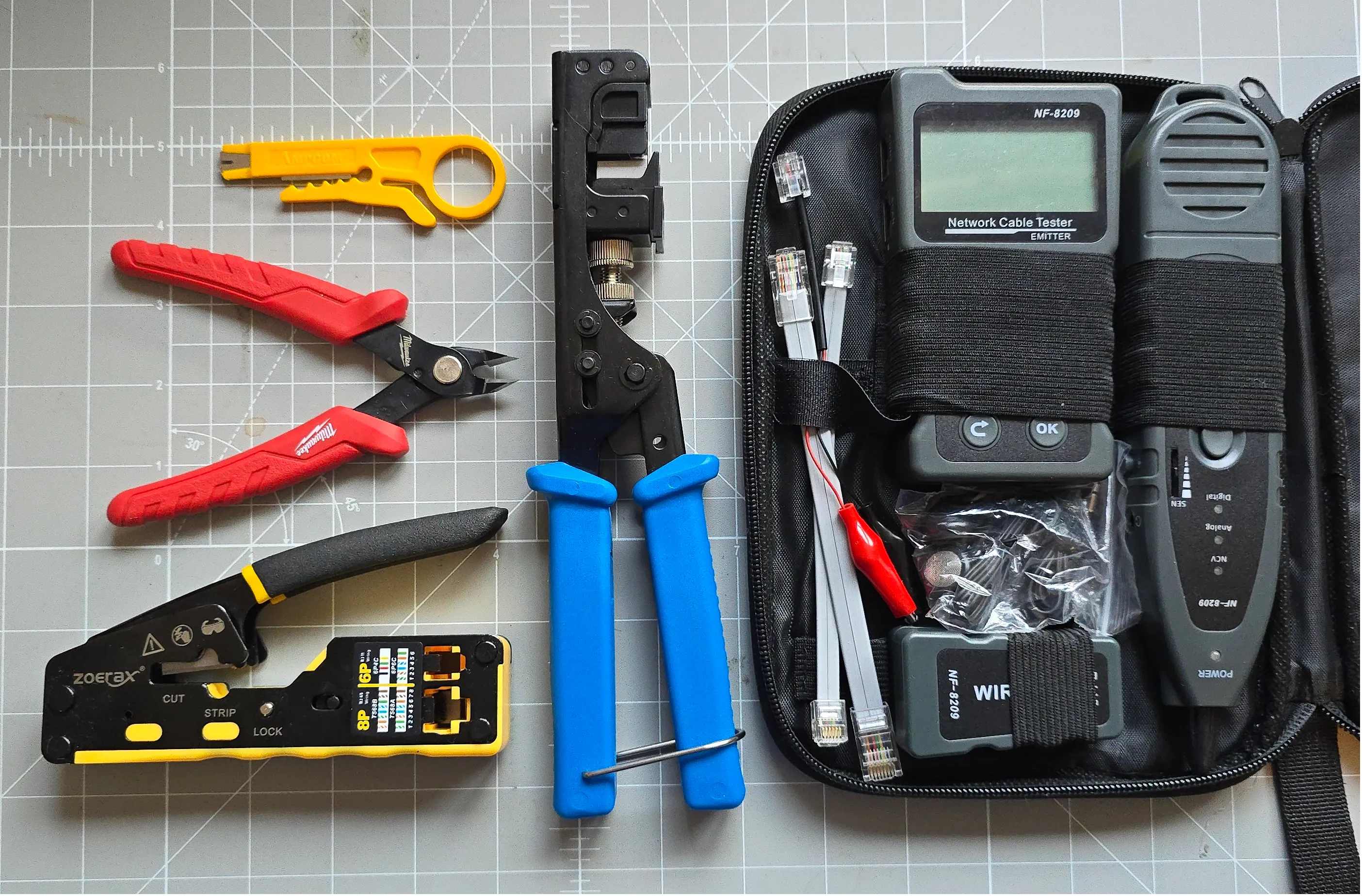
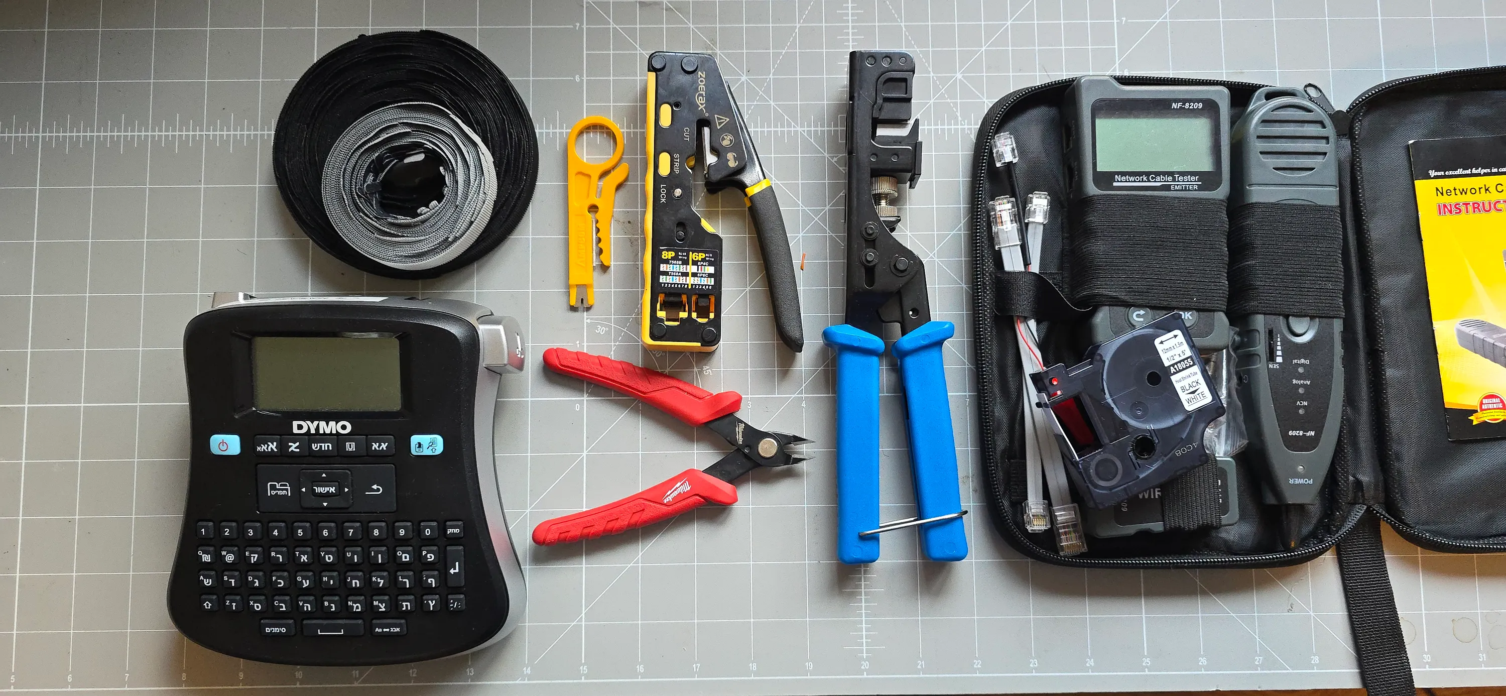
Tools
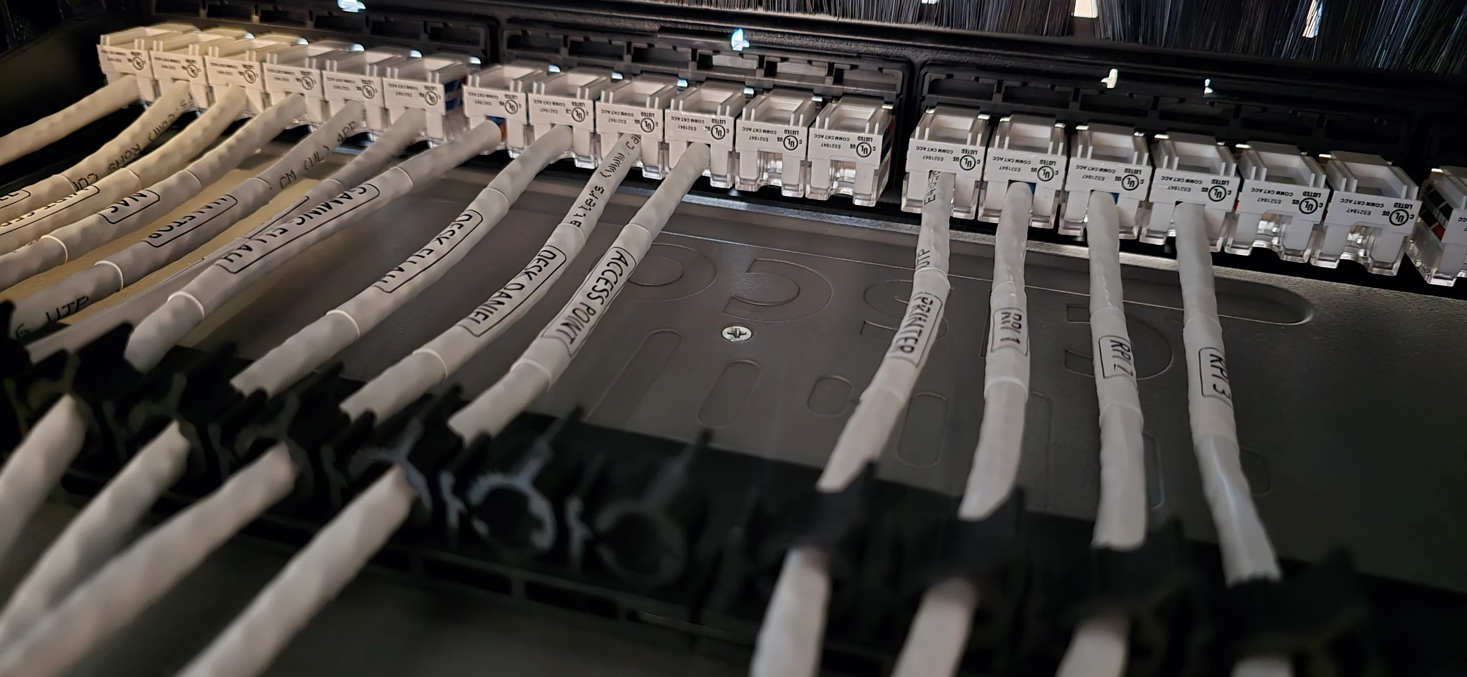
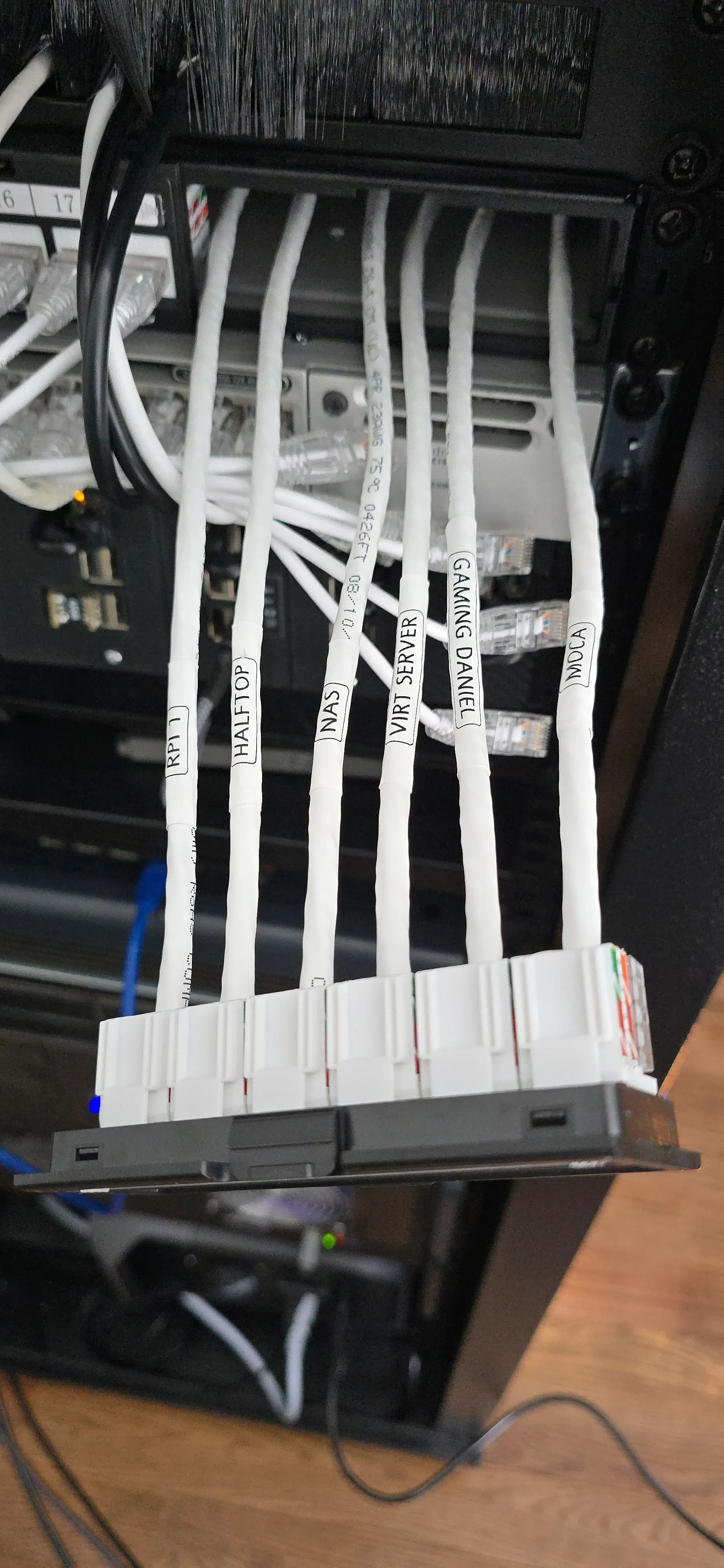
I have a 24 port keystone patch panel installed. This should give the front of the rack a better appearance and prevent any movement of the Ethernet wires (more on that later).
Unfortunately, the Krone punch tool I have doesn’t fit the keystone jacks I bought, so I had to buy a special tool for them that punches all 8 wires at once. That at least made things a bit easier for me. Just 24 potential punches instead of 192.
I used a network cable tester to test all the cables I made. It’s a cheap one, but it’s good enough for this application.
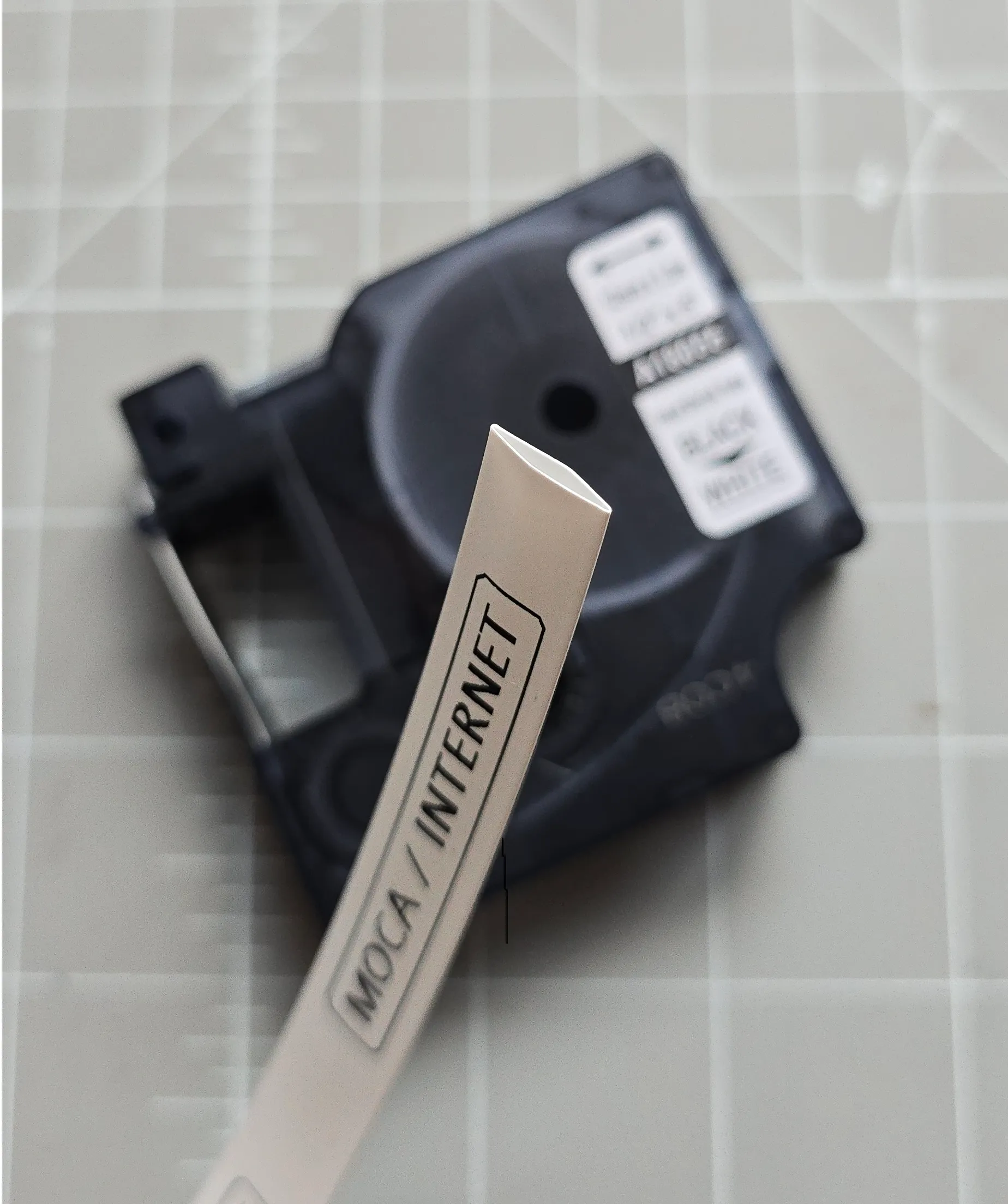
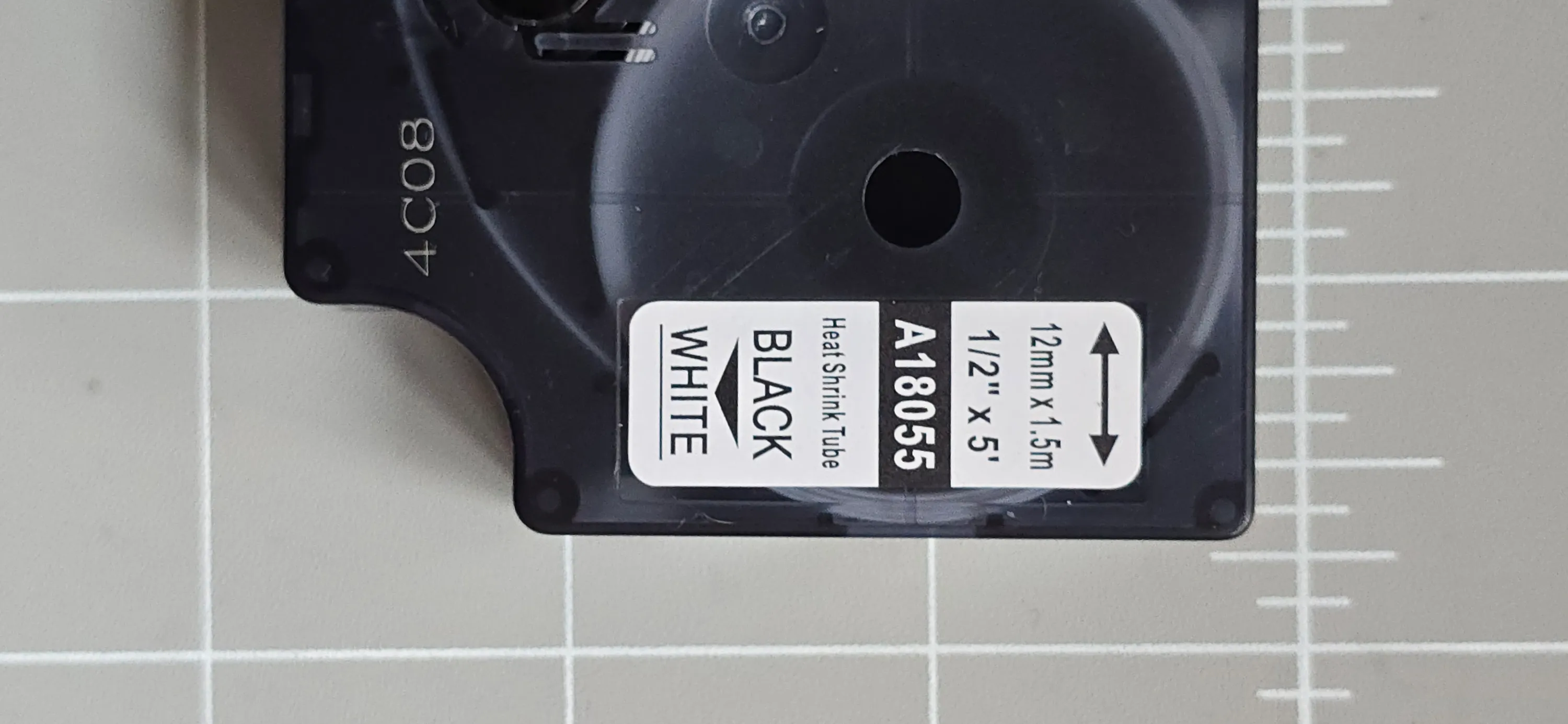
I used a DYMO label maker with heat shrink tape to label the cables. It’s so much better than folding regular labels or using cable ties with flags.
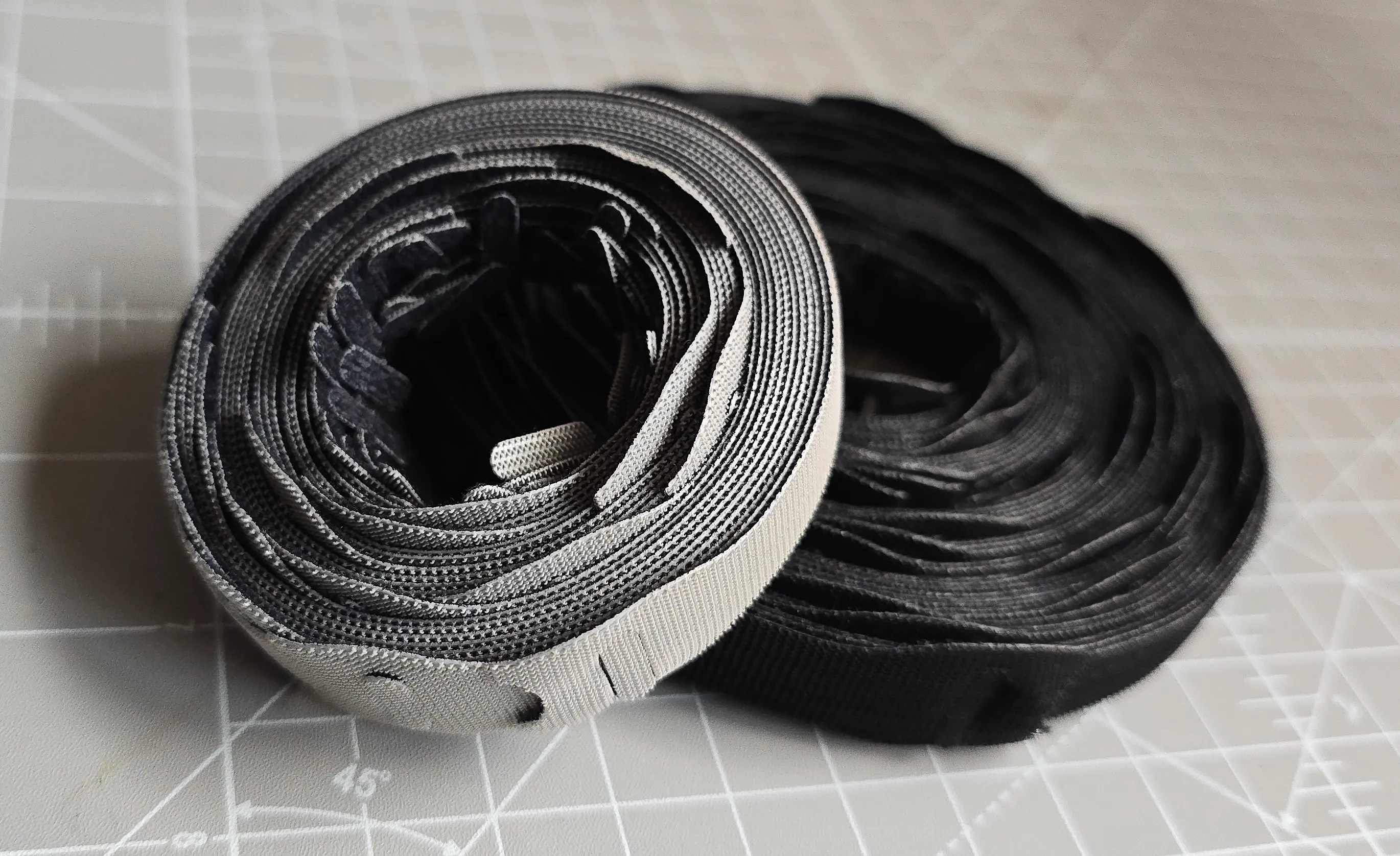
For tie downs I used Velcro straps. Grey for data, black for power.
Cabling
Cable Types
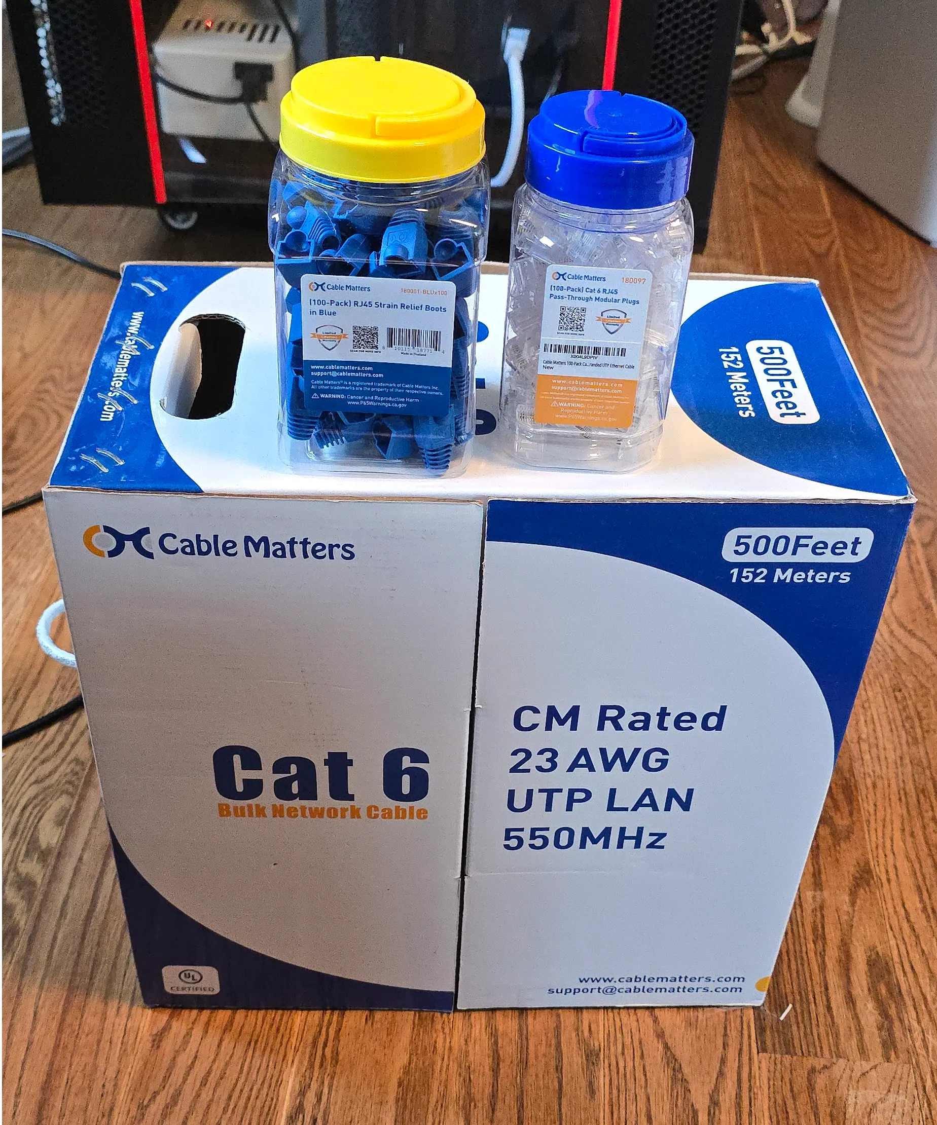
I chose CAT6 cables because I’m planning to upgrade to 10Gbps in the near future and utilize PoE for cameras, APs and RPis.
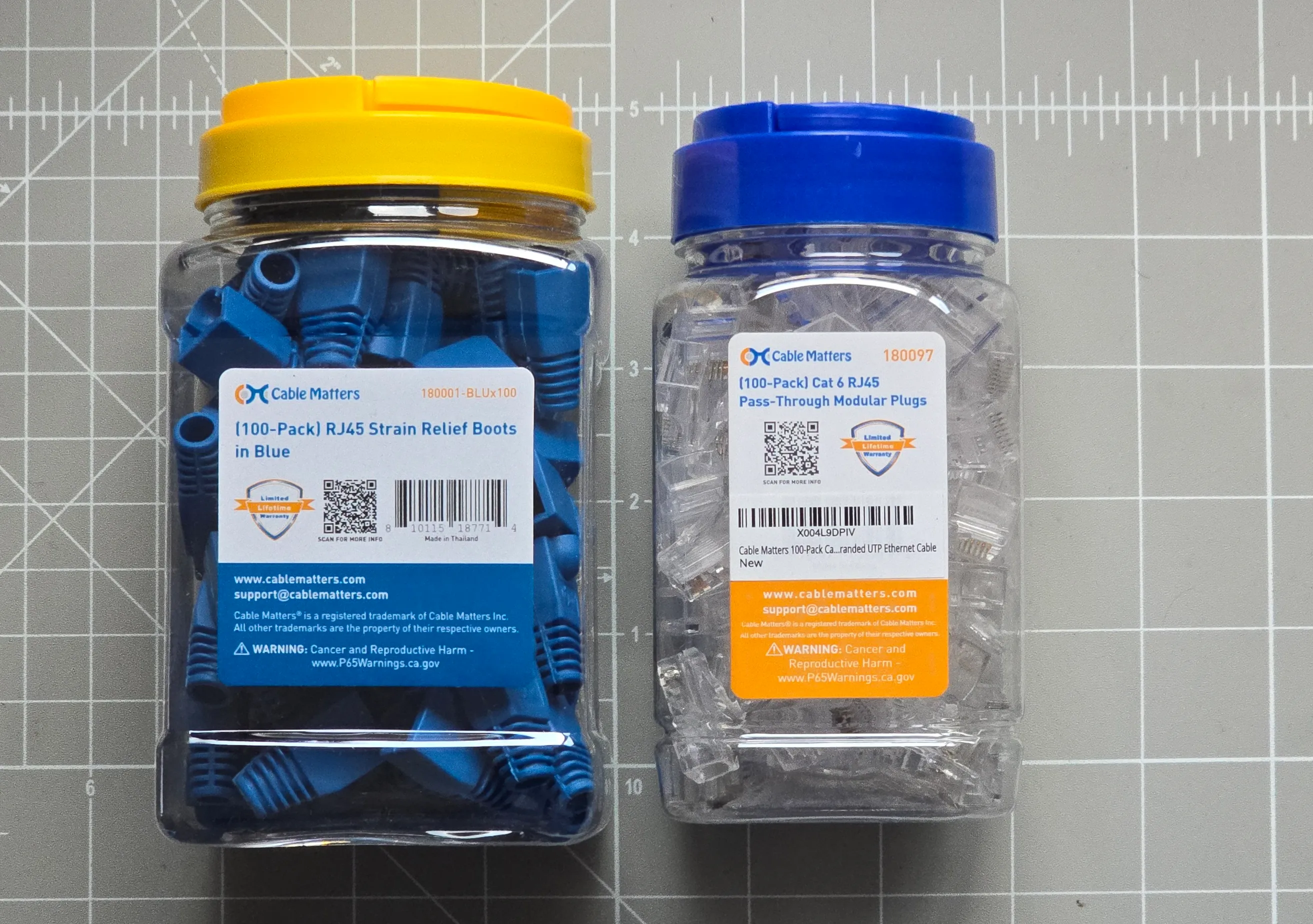
The cables will have one side punched to the keystones, which means they have to be solid core. The other side will be a RJ45 plug that will be directly plugged into each machine’s NIC, which is less than ideal for solid core. The risk is the core breaking inside the wire from movement because it’s not as flexible as stranded core, but since this is inside the rack and not going to move almost at all, it’s probably fine (All the potential movement is from unplugging at the switch, which will be done via stranded core patch cables, thanks to the patch panel).
The alternative for this would be keystone couplers and stranded core cables at both sides, but I’ll have some long cable runs for PoE cameras and APs, which are better done with solid core. I could have a mix of stranded for short runs and solid for long runs, but that would mean buying two types of plugs, keystone jacks and cables, which I don’t want to do.
The patch cables are just off the shelf regular CAT6 short stranded core cables. They are not perfect, some of them are a bit too short and are a little too tight for my liking, but that’s not a big deal.
I used to make the patch cables myself, but there’s enough work here that I decided to make my life a little easier. Maybe in the future I’ll upgrade to custom length patch cables that will look a little better and put less stress on the ports and less strain on the cables themselves.
Patch Panel Order
The order of the cables on the patch panel matters because the switch’s ports are not all the same.
It has 48 ports. All of them are PoE with the same spec, but only 12 are 10Gbps and they are all on the right, which is a bit inconvenient because it means my short patch cables won’t reach from some ports in the panel.
I could make custom length cables, but it would still look messy.
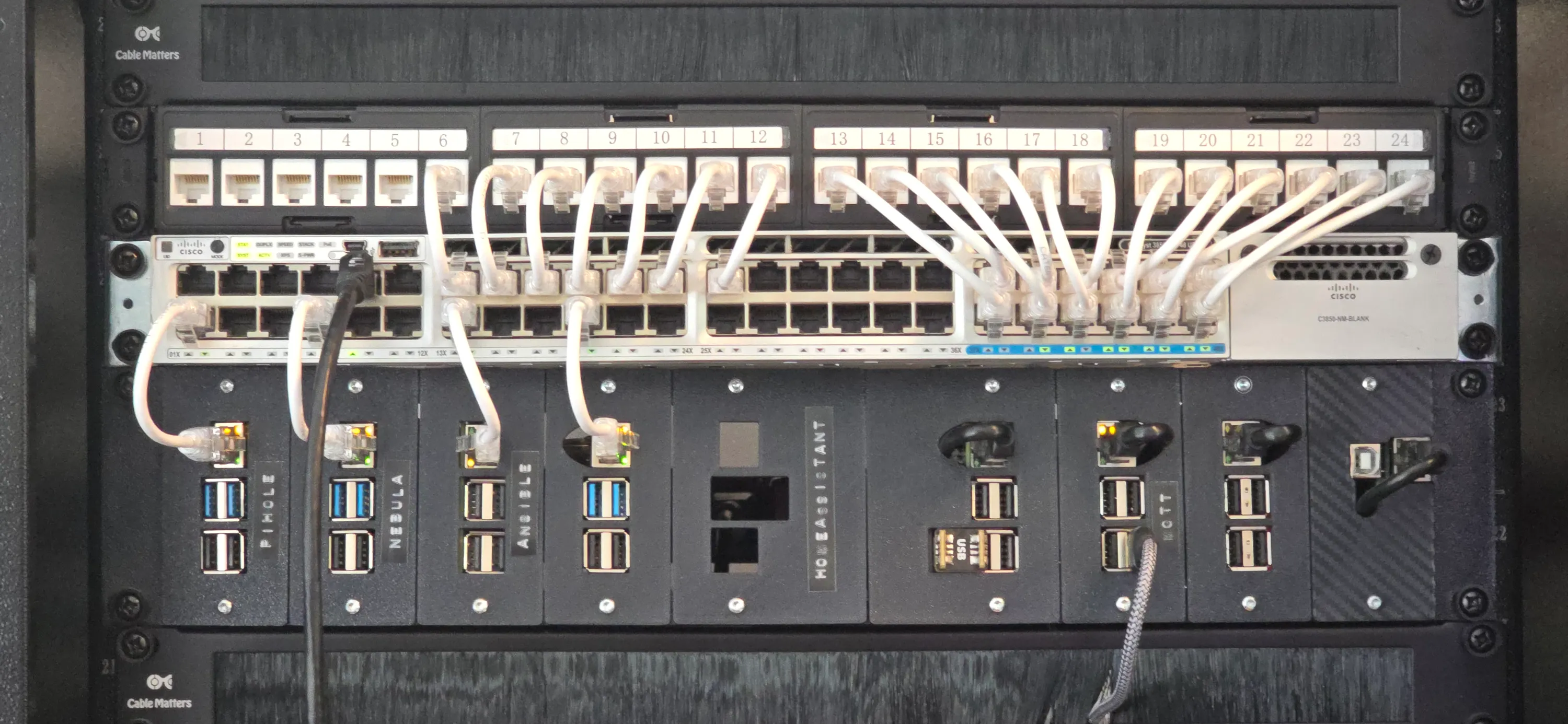
For this reason, I’ll dedicate the rightmost 12 ports of the patch panel to machines with 10Gbps potential.
This means that all the RPis and the printer, which are 1Gbps, all start from port 13.
This results in this strange configuration of patch cables:
Phase 1 - Network
As mentioned, that first step is network cables.
This will be divided into two parts - PoE and non-PoE.
Phase 1.1 - Non PoE
The non-PoE machines are trivial. There should be no risk to the machines or the data on them. I’ll just make sure there is no important data transfer happening like a backup or something before unplugging any machine.
My DHCP is my PiHole running on a Raspberry Pi powered by PoE, so I’ll make sure that’s still up while making the changes to all other machines. That way, there’ll be no limbo state when reconnecting to the network and all machines will get their correct IPs.
Phase 1.2 - PoE
PoE devices are trickier, especially since most of them are RPis running off SD cards or USB SSDs. This is a real danger for data corruption.
I’ll gracefully shut down any important machines before unplugging and YOLO the rest.
I connected my AP via a temporary cable straight to the switch just to keep the WiFi alive and have internet on my phone while I work. That way I can also check that services are coming up from my phone while my main computer is still unplugged.
The PiHole RPi will be the last to be disconnected for the same reason mentioned earlier.
Phase 1.3 - External Runs
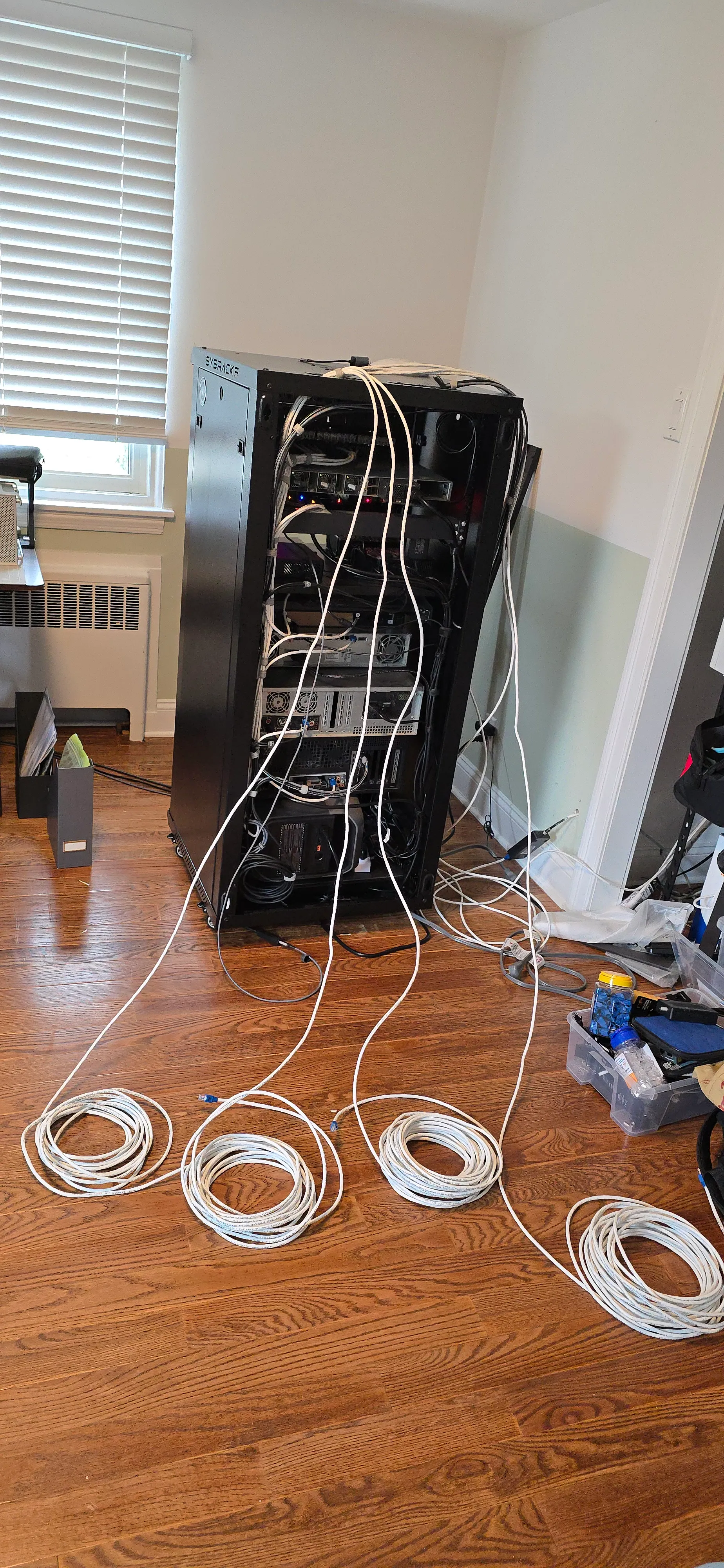
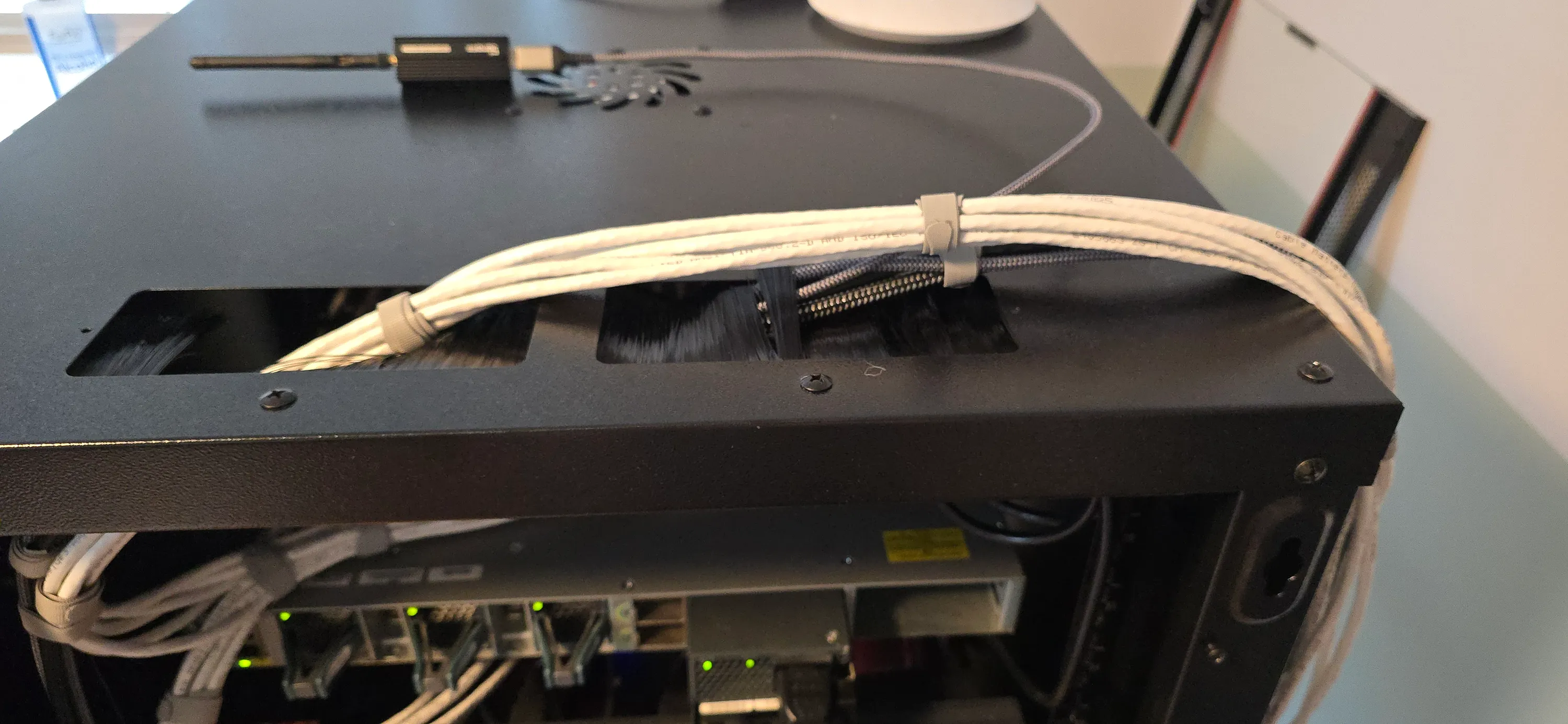
After all the internal cables are routed, I’ll add the long cable runs that go out of the rack.
These include APs, cameras, a laser printer and cables for my desk and my wife’s desk, for her desktop which isn’t racked, and for our work laptops, which will benefit from a wired connection for video calls instead of relying on WiFi.
Phase 2 - USB and Video
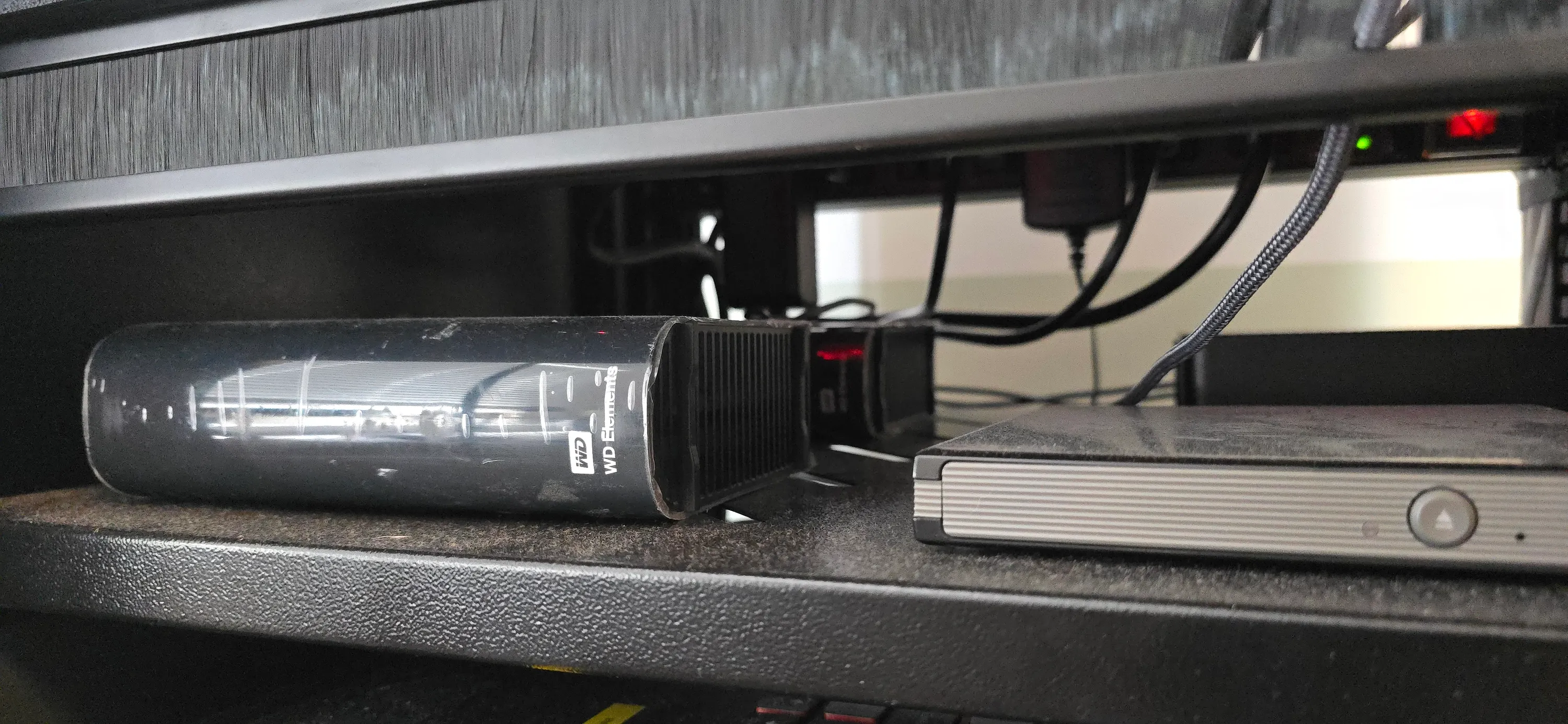
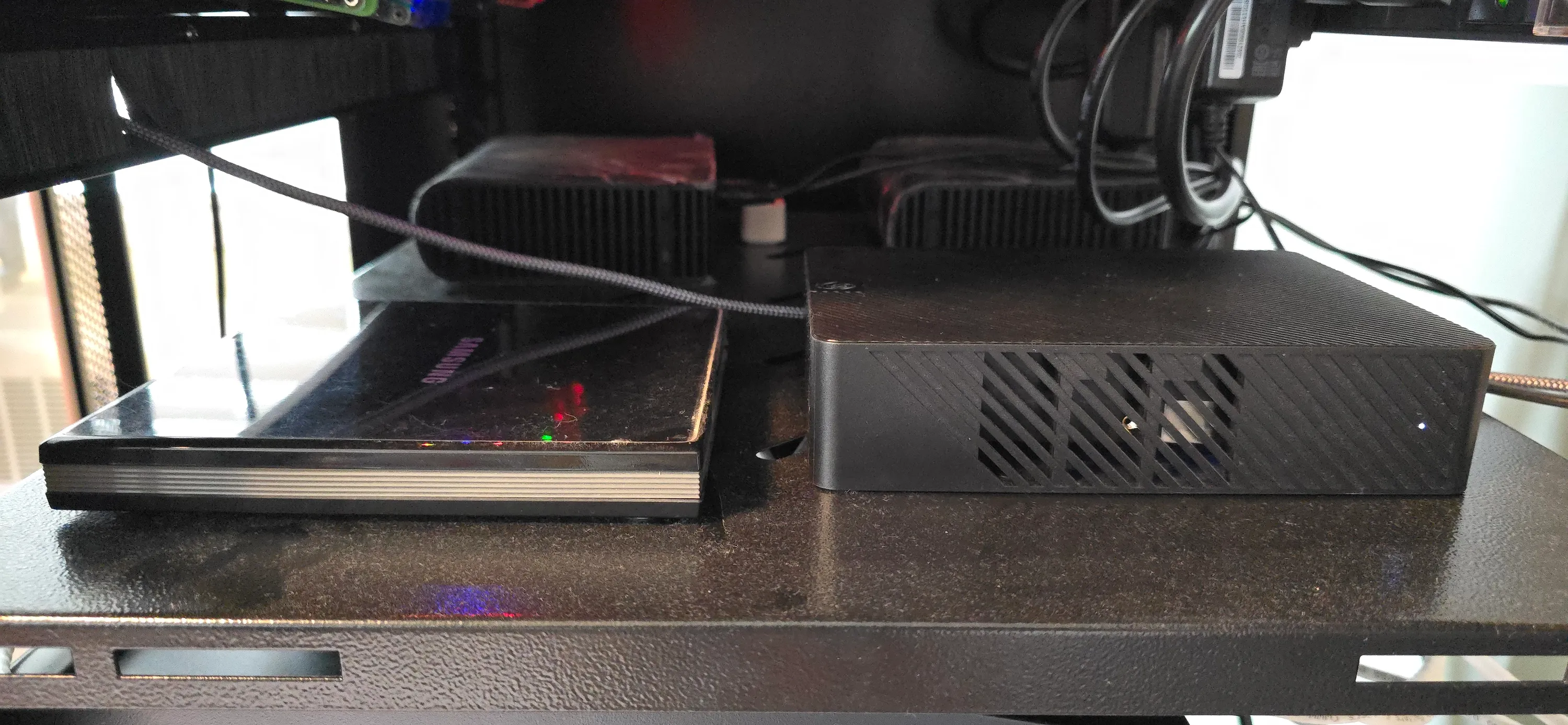
I have a few external USB HDDs that are passed to a VM on one of my machines. Unplugging them and plugging back in will not be seamless and might even be risky.
I have to at least unmount them in the VM OS, but I went a step further and brought down the whole VM because I don’t trust the host to recognize them properly and pass them through in the same order.
After bringing the VM down, I unplugged both power and USB from the HDDs. Once the USB cables were rerouted, I left the VM down and the HDDs powered off until the power cable stage was done. There’s no sense bringing everything up just to take it down again.
I also have a Zigbee dongle with a long USB extension cable plugged into a PoE RPi that’s running Mosquitto MQTT server and Zigbee2MQTT for smart home. I rerouted that while the RPi was down for network cable rerouting. No sense in bringing it down twice or making sure that it’s recognized properly after unplugging while it’s running. If I do it while it’s down, the software will not notice anything changed and it will be seamless.
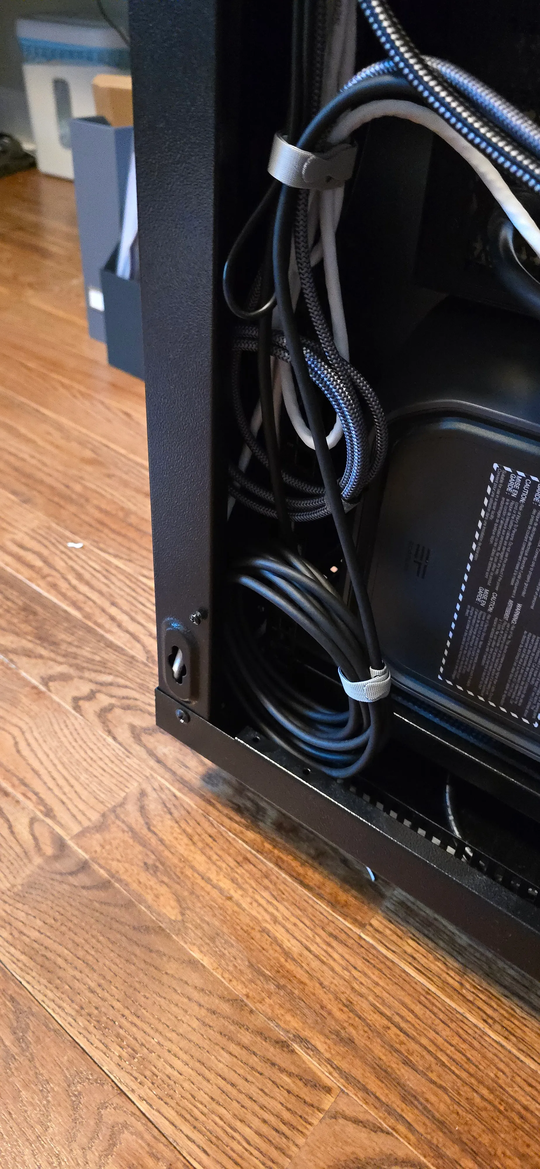
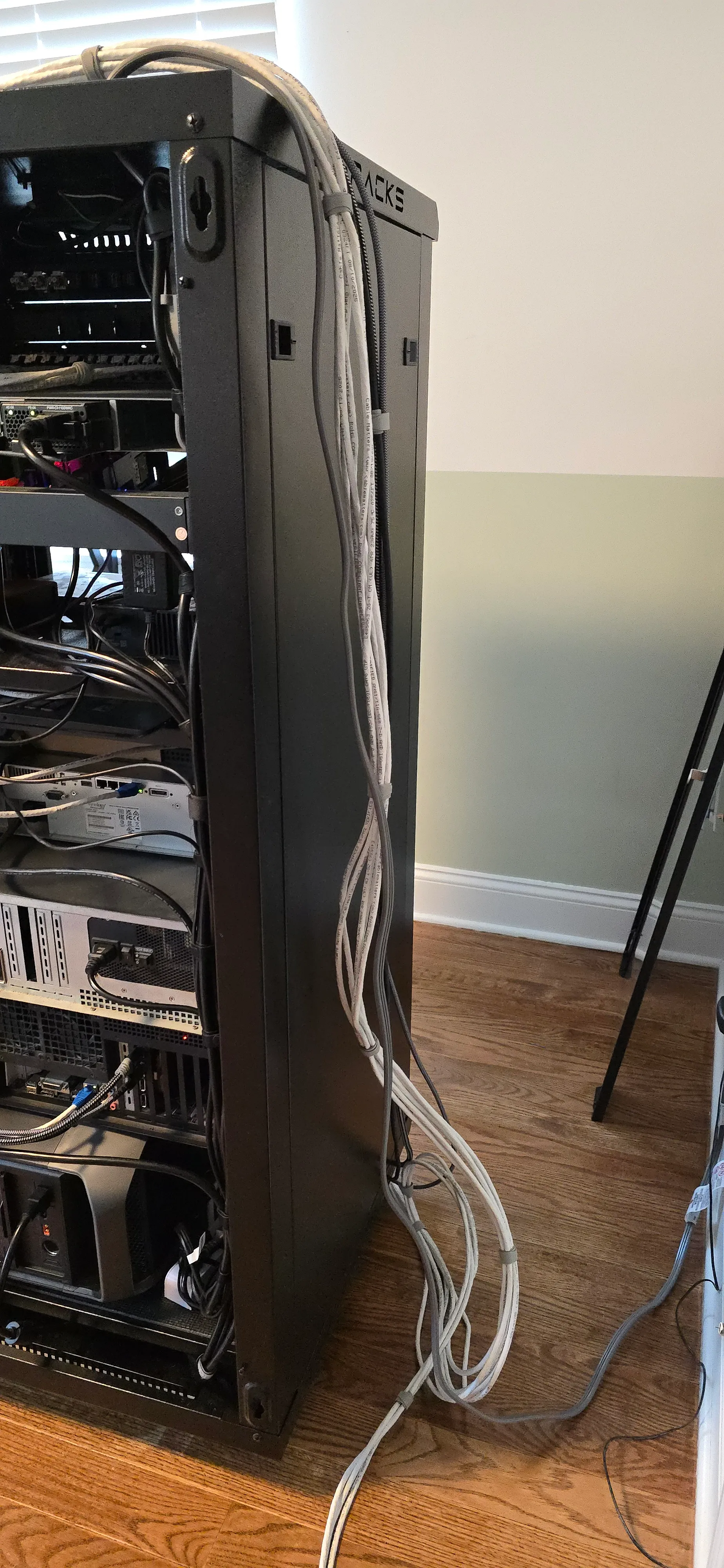
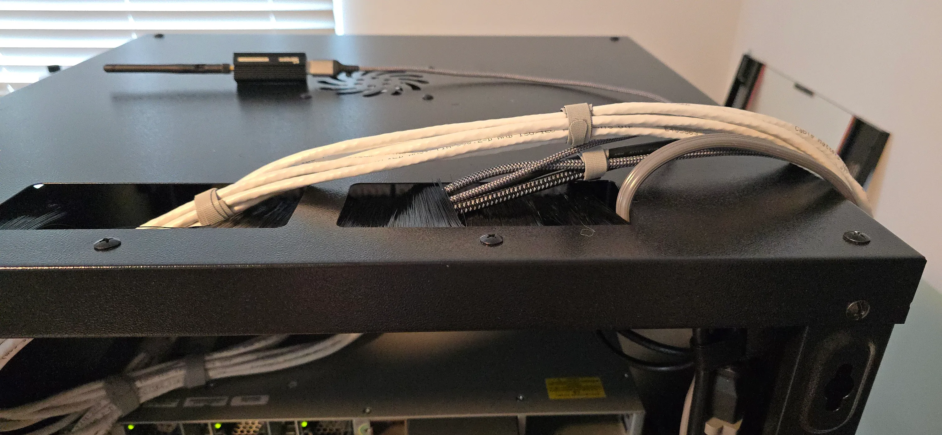
Finally, I have a long USB extension cable and two video cables running from my racked gaming PC to my desk. They are coming into the rack from the top, with the long runs of ethernet cables, and are not risky to unplug at all. I’ll bundle them up with the internal USB cables and roll the slack in loops at the bottom of the rack.
Power Bundle
I chose to just use the power cables that I have and not make custom cables. This makes the job simpler and tool-less but sometimes less convenient, since I have to take care of extra slack with thick cables.
Topology
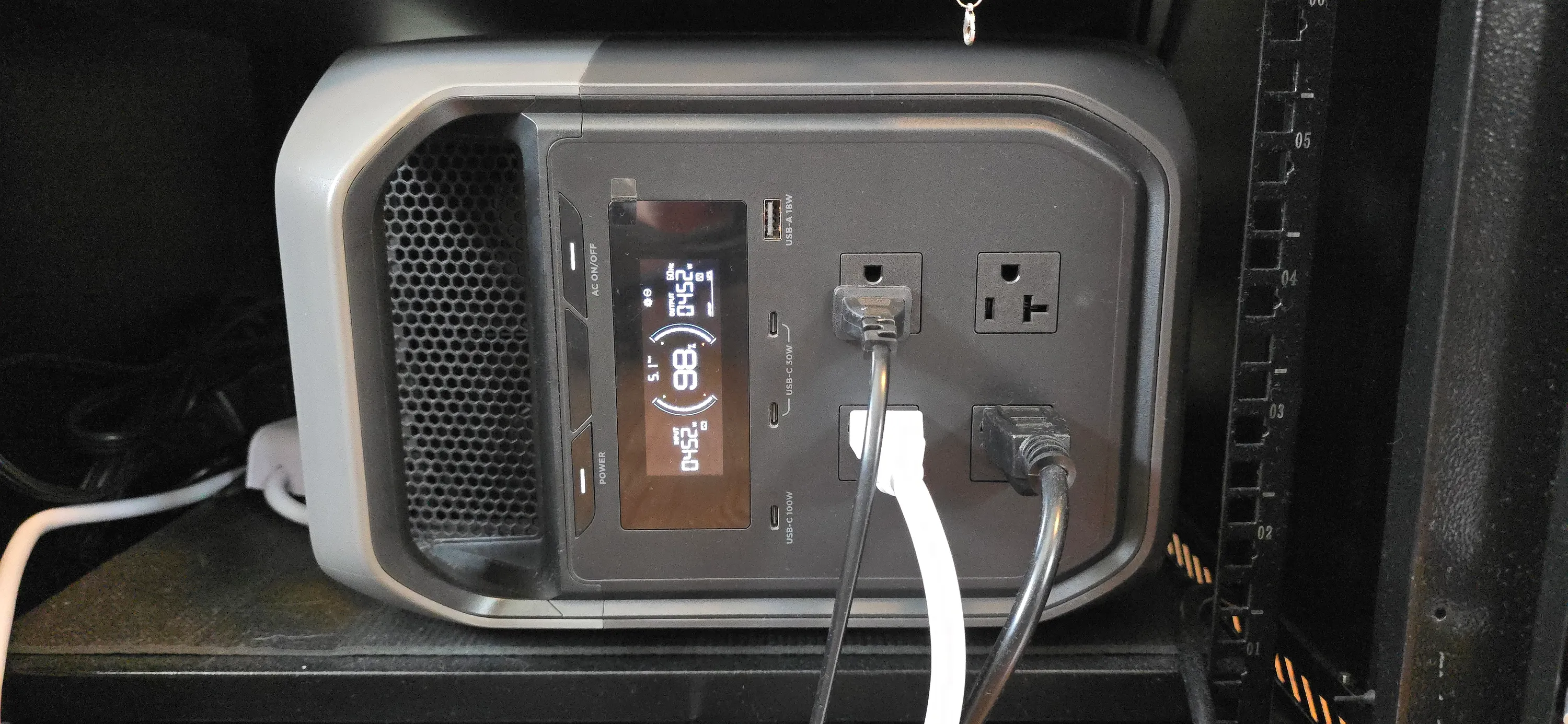
The rack is fed from a single cable, connecting to an EcoFlow Delta 3 Max power station. It’s not a full-fledged UPS, but it has the important UPS features that make it suitable as a backup power source. Namely, 20ms switching.
It lacks network connectivity and NUT, which is a shame, but it can provide 3kW of power at the price of a 1kW full UPS, so that makes up for it. I need that kind of power so that I can have my 3D printer protected from brownouts.
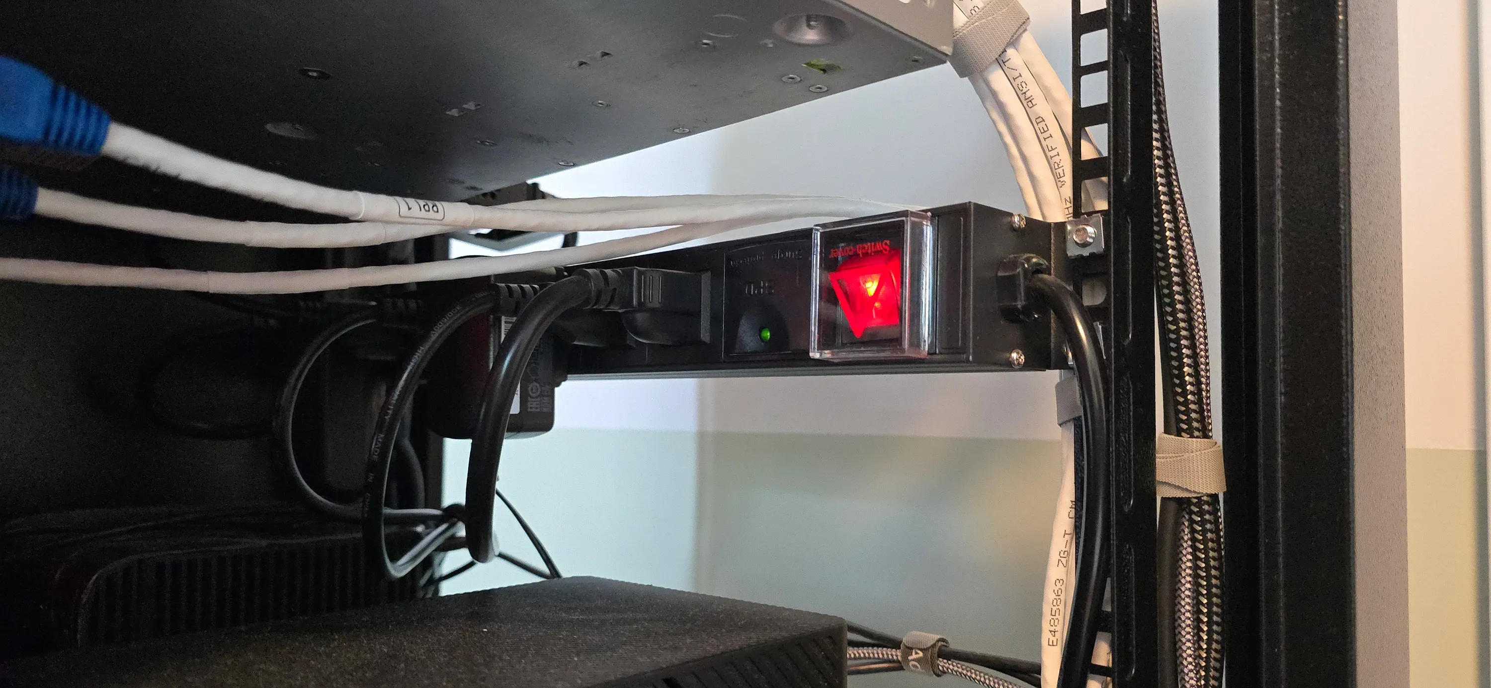
Connected to the power station, there’s a rackmount PDU at the top of the rack and a regular power strip at the bottom. These feed everything. The more power-hungry computers are connected to the PDU since it’s rated for higher current and it’s fixed in place, so accidental unplugging is less likely.
Order of Operations
For easier maintenance in the future, I’ll bundle the cables in order of the probability of them having to move.
Since all machines apart from my gaming PC are headless, I’ll power all of them down first instead of doing it as I go from my phone. The exception to this is my halftop (laptop with the screen removed), which still has its battery, acting as a built-in UPS, so it can stay on for the duration.
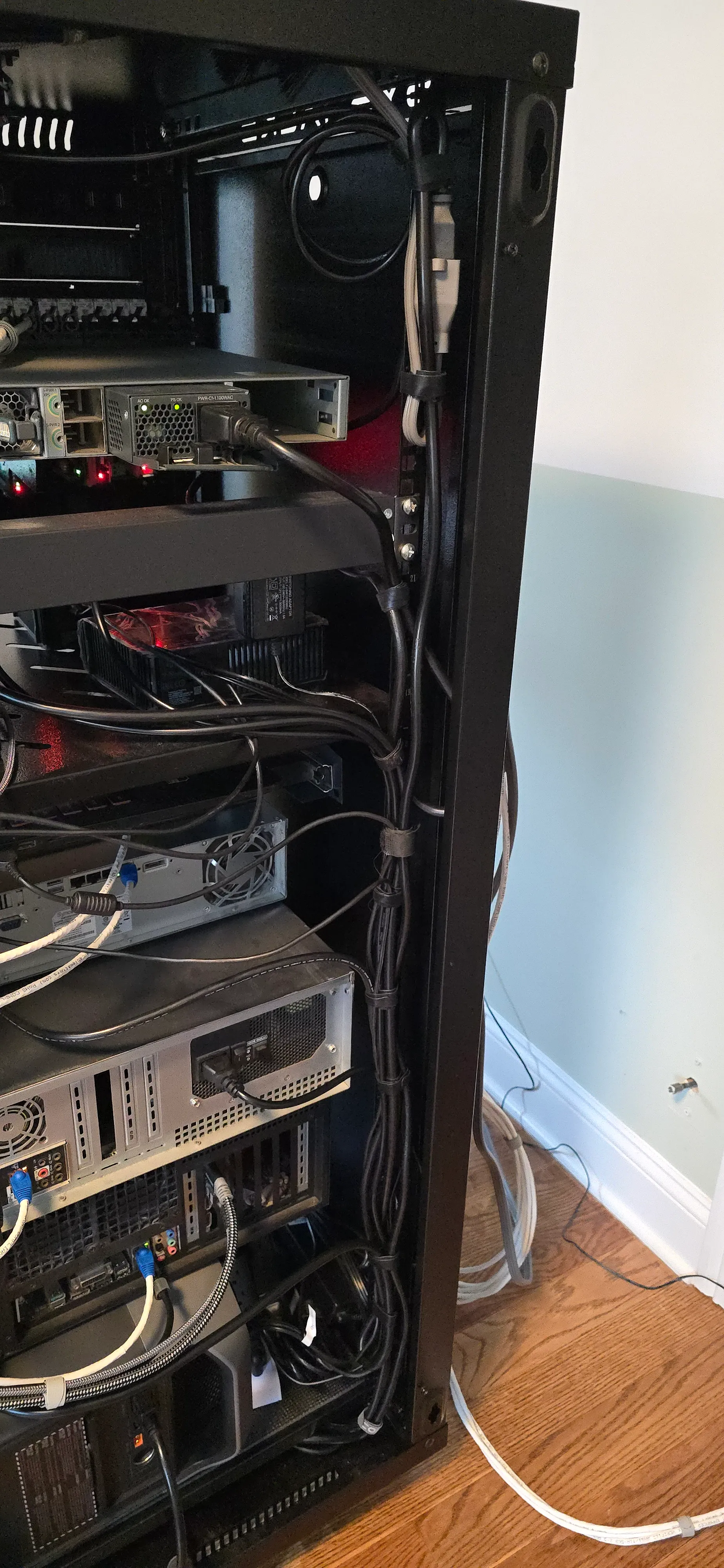
The PDU, gaming PC, NAS and virtualization server are the first to be bundled. They have the thickest cables and are least probable to have to move.
Next, the two laptop brick power supplies’ cables (for the halftop and the 1U server, which is a laptop motherboard in an enclosure) are joined to the bundle and the bricks themselves are set at the bottom of the rack. They have thinner cables and might move because I might want to find a better place for the bricks.
The HDD power cables are bundled next. They are the most probable to move because the HDDs themselves are portable and sitting on a shelf, not fixed to anything. They are taking up valuable rack units that I might want to free up if I decide to add more rack-mounted equipment.
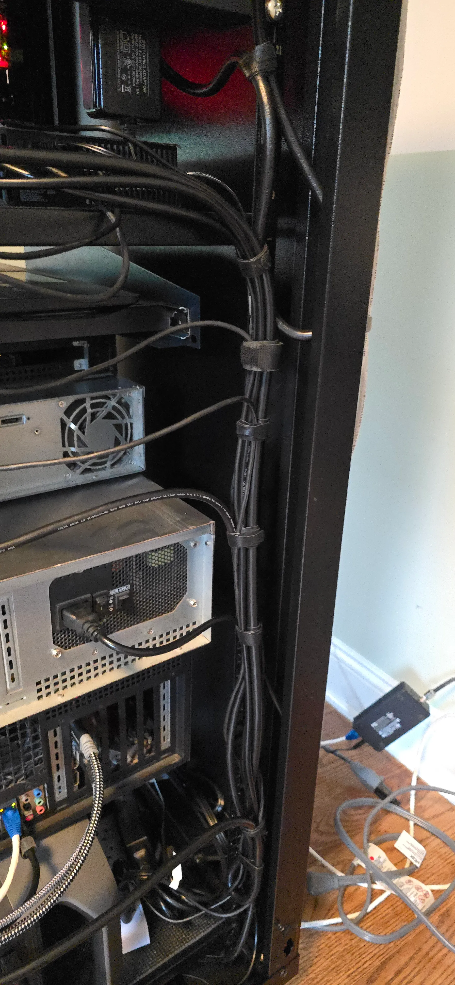
Lastly, the main power cable coming into the rack has to move. It currently comes in from the bottom slot of the rack and I want it to come in from the top, bundled with the rest of the cables coming in.
This is not a big deal since it’s connected to the power station. Removing it will not affect anything as the power station will keep everything powered long enough.
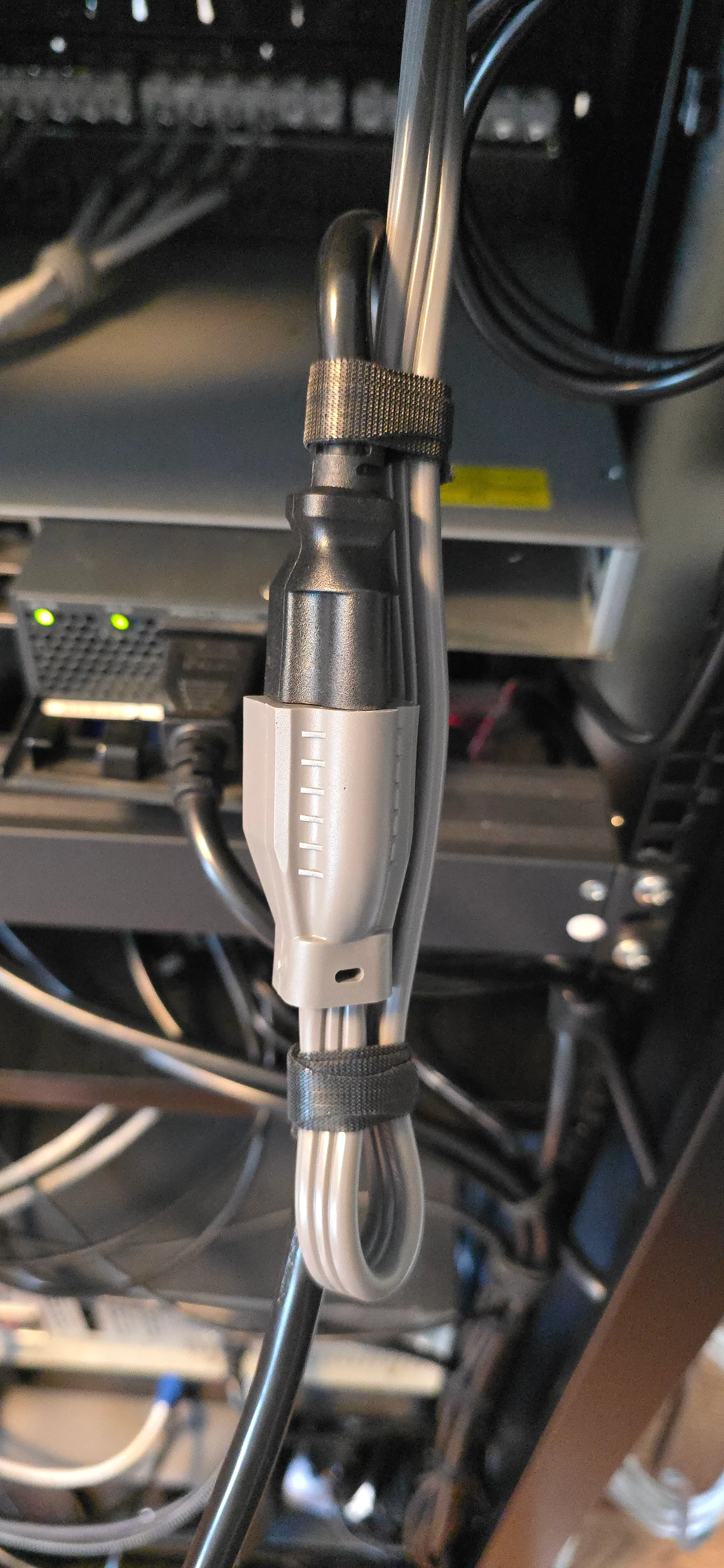
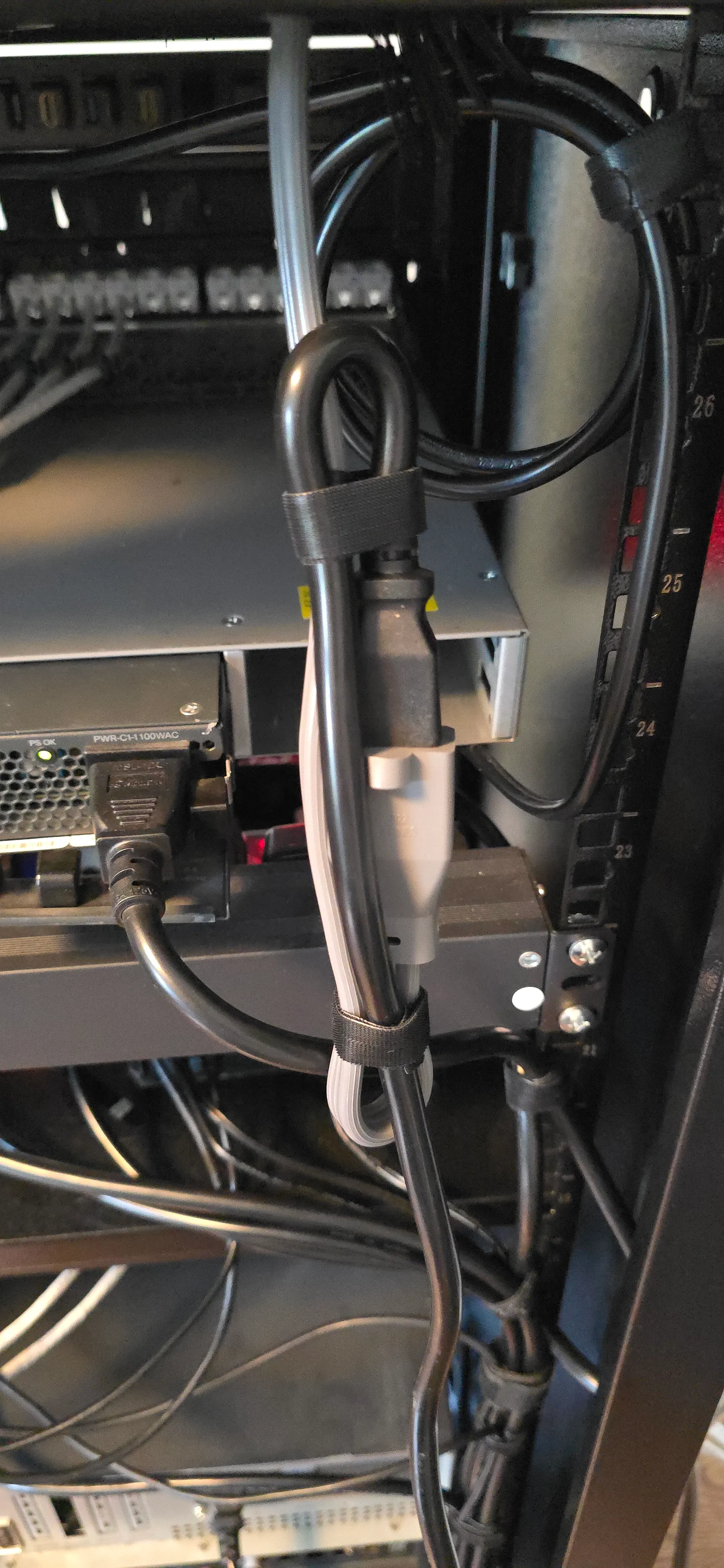
The main power cable is connected via an extension cord, so to minimize the risk of it getting disconnected accidentally if it gets snagged on something, I made a loop where the connection is and tied the ends together. This way, if it gets pulled, it doesn’t disconnect (up to a point).

Epilogue
Back Panel
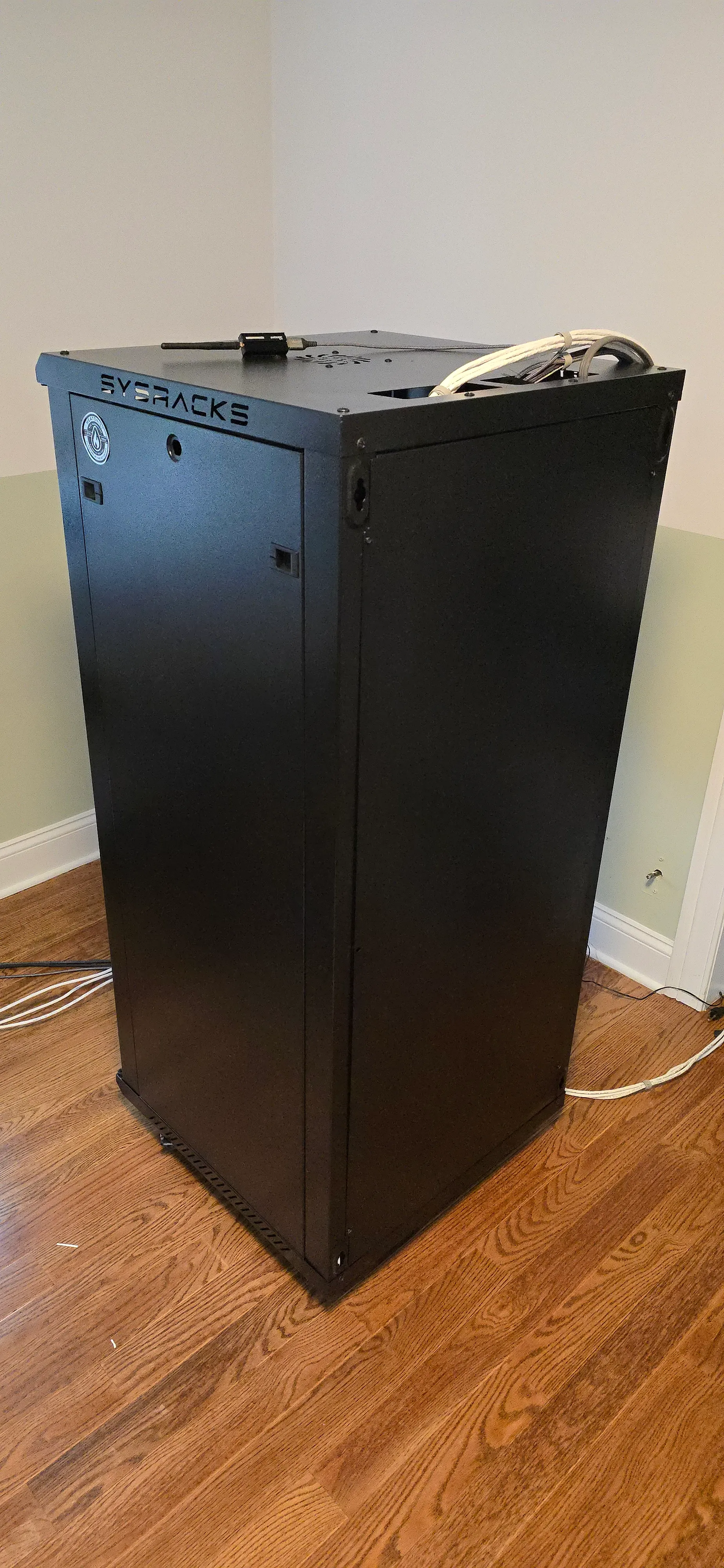
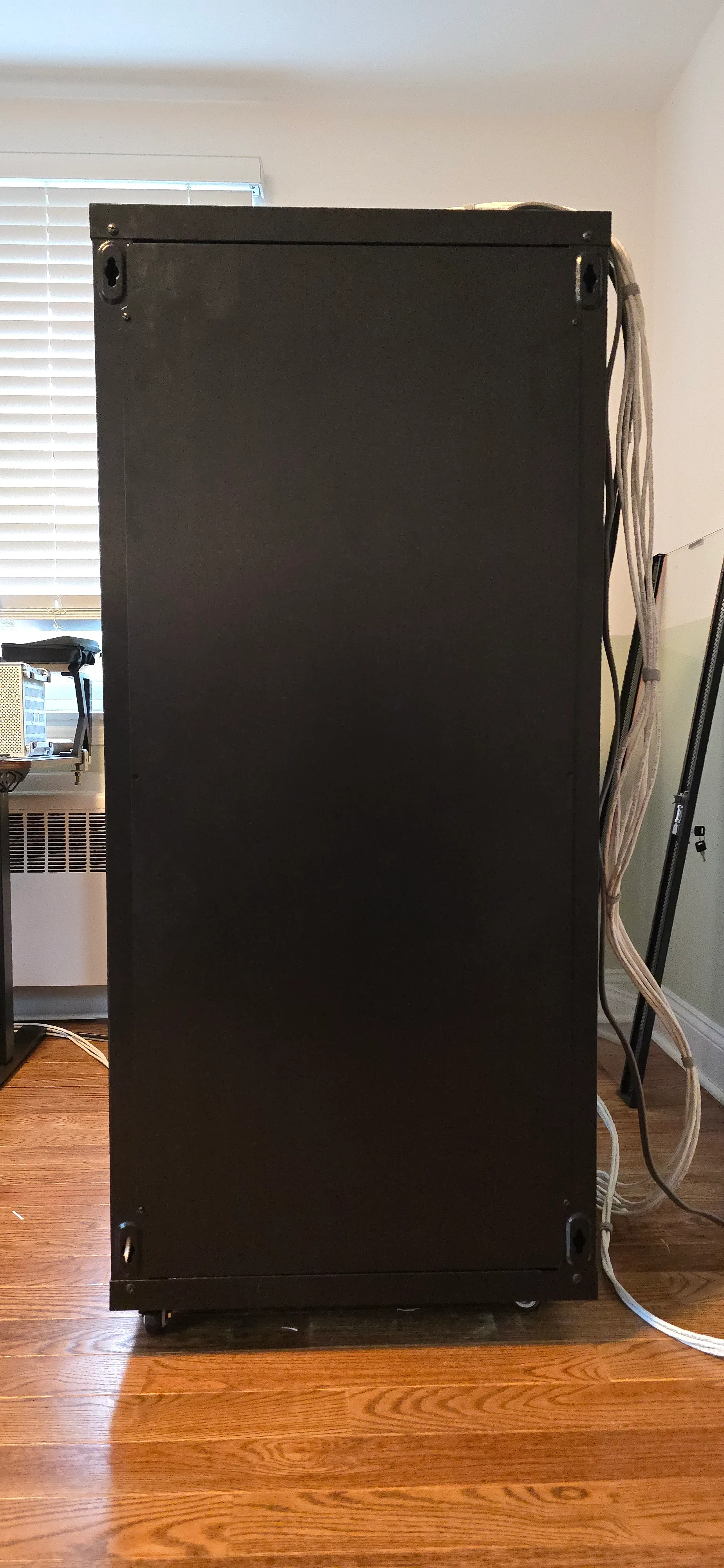
Now that there are no cables coming out of the back of the rack, I can finally close the back panel.
Closing it makes the rack look much better and helps with the noise, but I suspect it hurts cooling, so I’ll keep the panel off the rack for now. I have some ideas for turning it into a door for easier access (it’s currently held on with 6 screws and gets wobbly when removed), and I’ll maybe add some fans so cooling is better whenever it’s closed.
Reflection
Before getting this done, doing anything physical with the rack was a pain. Even moving it slightly was a juggling act of kicking floor cables so they don’t get under the wheels and trying not to pull any important cables and disconnecting the house from the internet.
Now it’s a breeze. I can roll it around the room and access all sides. Even just looking at it in this state gives me pleasure and relief.
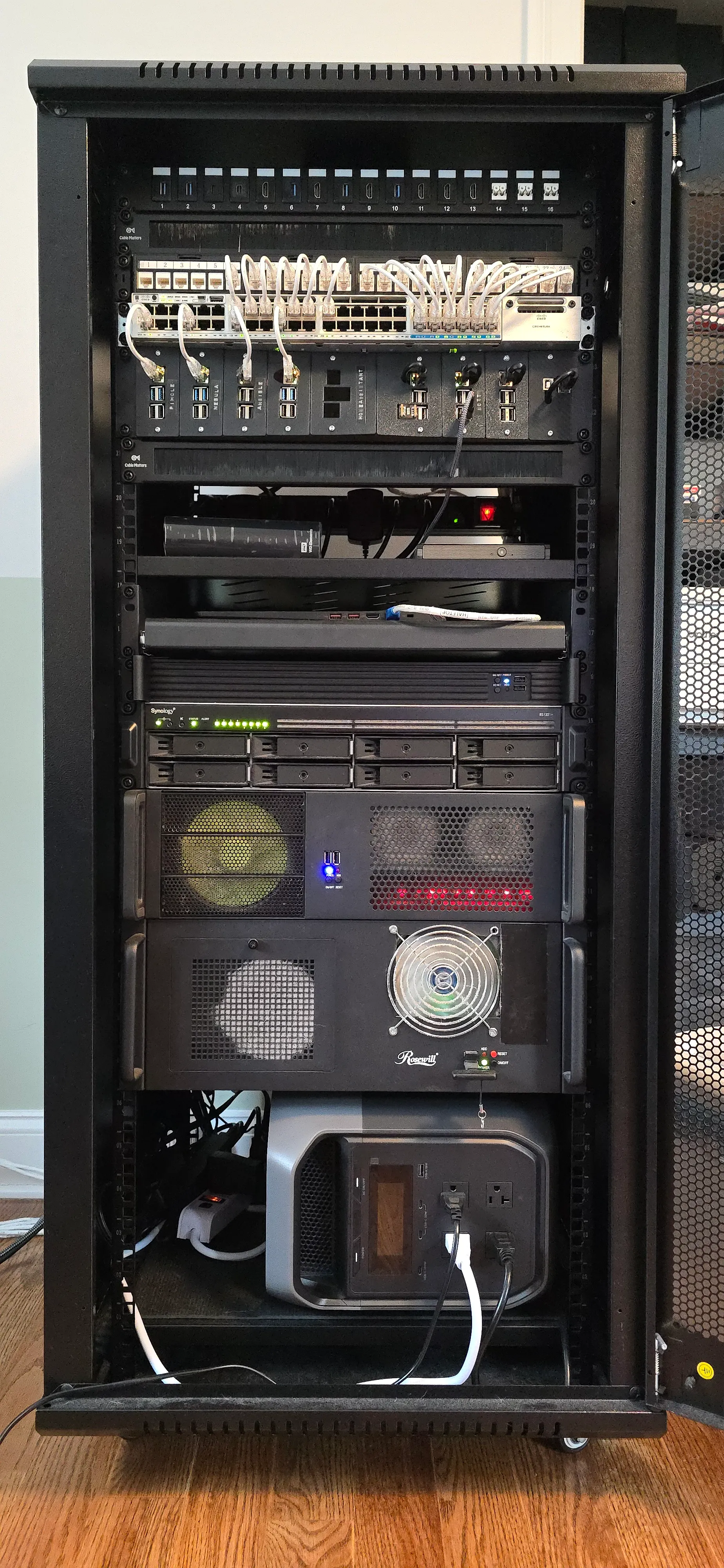
I’m finally proud to show pictures of the rack. It’s tidy and clean and I don’t have to give excuses for the mess.
Future Work
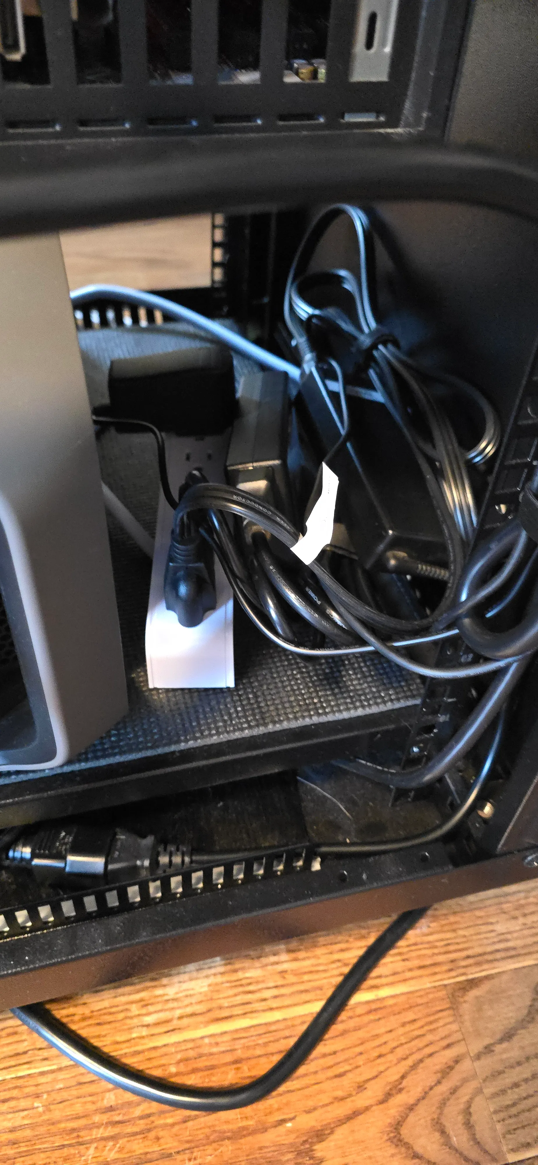
There’s still some work to be done to tidy the power brick cables at the bottom, but that’s not a big deal.
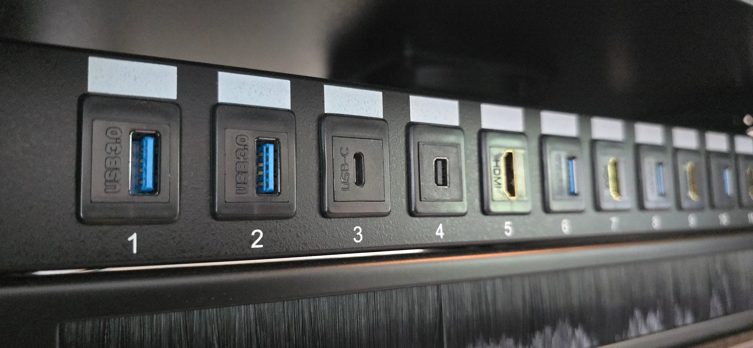
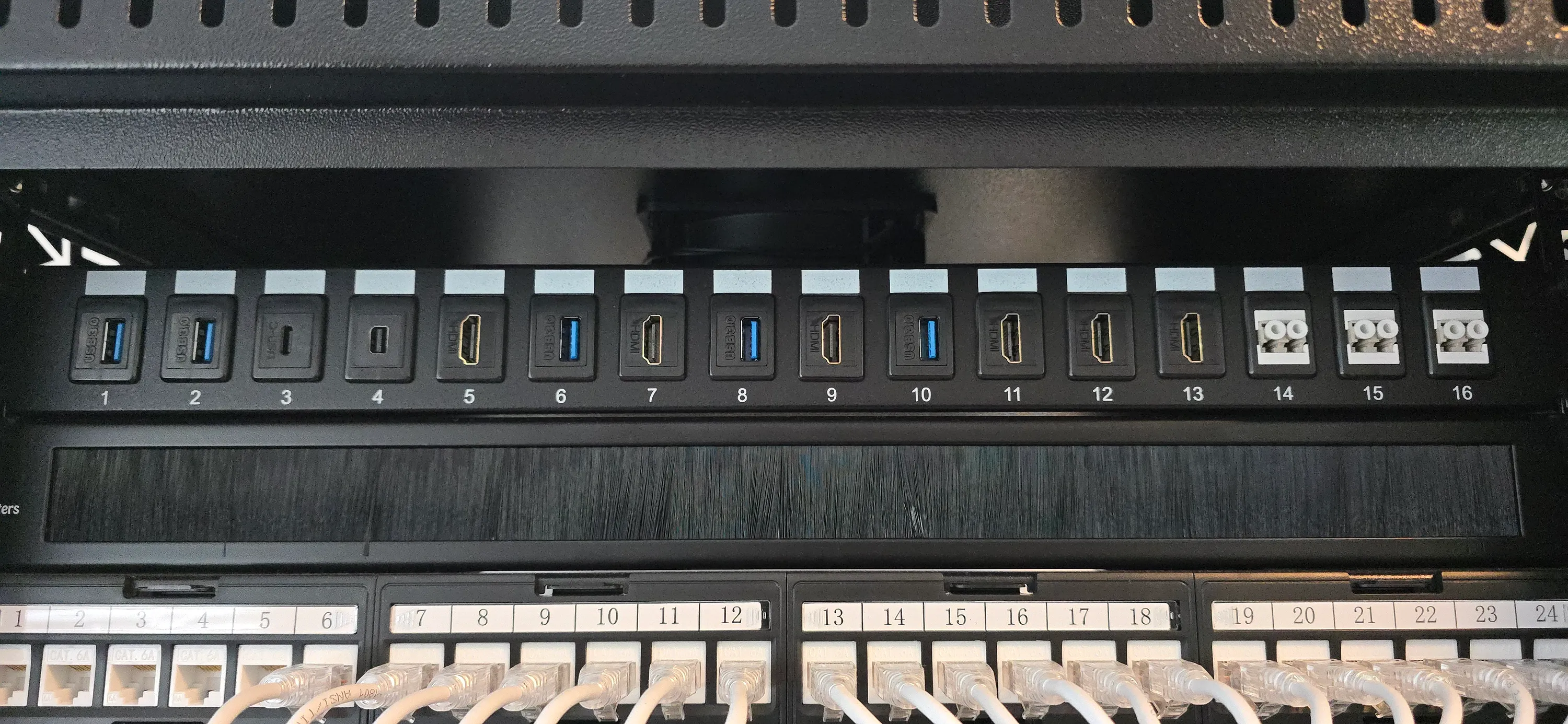
You can see in the photos of the front of the rack that there’s another patch panel at the top with USB-A and USB-C, HDMI, DisplayPort and fiber ports.
That used to be connected to some of the machines for easy access, letting me plug external devices into them without fumbling around the back.
When I moved all the equipment to the new rack, I didn’t connect them. This is a future project and will be much easier now with all the cables managed.
I also plan to add a KVM to the rack for video output to some of the headless machines for easier maintenance. This will also be much easier with all the cables managed.