I don’t really know how this happened, one day I picked my radio up and noticed the left gimbal isn’t centering correctly. I tried trimming it, but it wouldn’t center to the same position every time so it didn’t help, the next time I moved the stick, it would need re-trimming.
Diagnosis
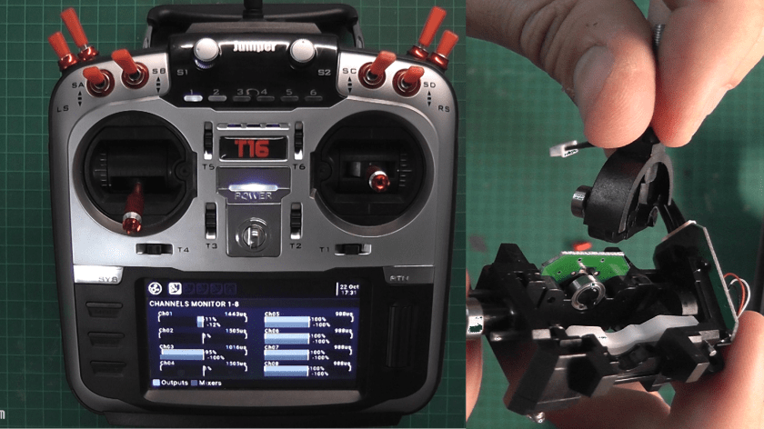
When I move the gimbal to the left, it reaches -100%, but on the right side it would only reach about 90%.
If I move it up and down while it’s all the way to the right, the value would suddenly jump to 100% and return to 90%. When this happens I could feel a bump in the movement.
Clearly something is physically wrong and not just electrically.
I initially thought something might be stuck inside and preventing the stick from reaching the end of it’s travel, but the stick reaches the end without problem. I started suspecting the potentiometer shaft is loose or stuck or maybe the potentiometer itself is defective.
Anyway, a teardown is needed.

Teardown
I took the radio apart and removed the gimbal to have a closer look. (The side slider needs to be removed also to give access to one of the gimbal screws).
I didn’t see anything suspicious but I could feel the same bump when I moved the stick.
I looked closely at the potentiometer movement, but it’s range is pretty narrow and the small (~5%) error I saw on the display is not clearly noticeable to the (my) naked eye.
A deeper teardown is needed.
I took the gimbal completely apart, then the problem became very obvious – the shaft coupling the stick and the potentiometer is broken.

To Repair Or Not To Repair
The radio is 5 months old and I heard good things about Jumper’s customer service, but I don’t want to wait a month for a replacement.
I also planned to upgrade the gimbals to the new hall effect ones that come with the “pro” version, so the replacement one would get replaced again anyway.
I decided to not request a replacement, temporarily repair my gimbal myself and order the new ones.
Repairing The Shaft
The two broken parts seem to fit together, there doesn’t seem to be any missing pieces, which is great, I can just glue them with Epoxy.
The shaft has a flat spot so there’s only one way it can fit the potentiometer. This means that any adjustments need to happen before the glue hardens, there’s no additional angle calibration on the potentiometer or the PCB.
I fully expect to not have a perfect angle. I don’t have any way to accurately position the two parts. the potentiometer is not indented so it can’t be used for indication or positioning and I don’t want to glue it together with the radio on.
I’ll glue it as straight as I can and compensate in the software. I might lose some range and resolution, but it will work as a temporary fix.

Making It Work
After letting the glue cure and putting the radio together, I tested the outputs on the radio.
I can see that there’s an offset of ~11% (out of 200% total, so a ~5% error, not bad). This means I glued the shaft with a very slight rotation.
Moving the stick, I can see that it returns to the exact same spot every time. Excellent! This means I can simply trim it and have the center point at the correct value. But is it enough?
Moving the stick to it’s limits shows 100% on the left and 90% on the right. This is due to the offset from before, this means that the left limit exceeds the limit of the potentiometer, leaving the last bit of travel undetectable.
If I simply trim the center point to where it needs to be, I would get an asymmetrical range.
To make it symmetrical, I would need to ignore the same amount of travel on the right side and scale the range to make use of the whole signal range.
This is done by using the curve and mixer option in OpenTX.
I configured a -11% offset on the input to provide the trimming action we wanted.
I defined a new curve to make the range symmetrical. The rightmost 10% of the range will report the same value of 90%, thus giving a range of -90% to 90%.
I configured the mixer for the channel to use the curve I defined and configured the weight to 111% to stretch the range from -+90% to -+100%.


Now I have the correct range and center point with the last millimeter or so of travel on each side of the stick ignored.
I’m pretty happy with the result.
I hope this helps anyone with the same problem.
