FPV Repair Shop #1 - Crashed Holybro ATLATL-HV VTX Repair [Antenna, Connector, Diode]
![FPV Repair Shop #1 - Crashed Holybro ATLATL-HV VTX Repair [Antenna, Connector, Diode]](/projects/fpv-repair-shop-1/images/20191015_224632-e1571182729160.webp)
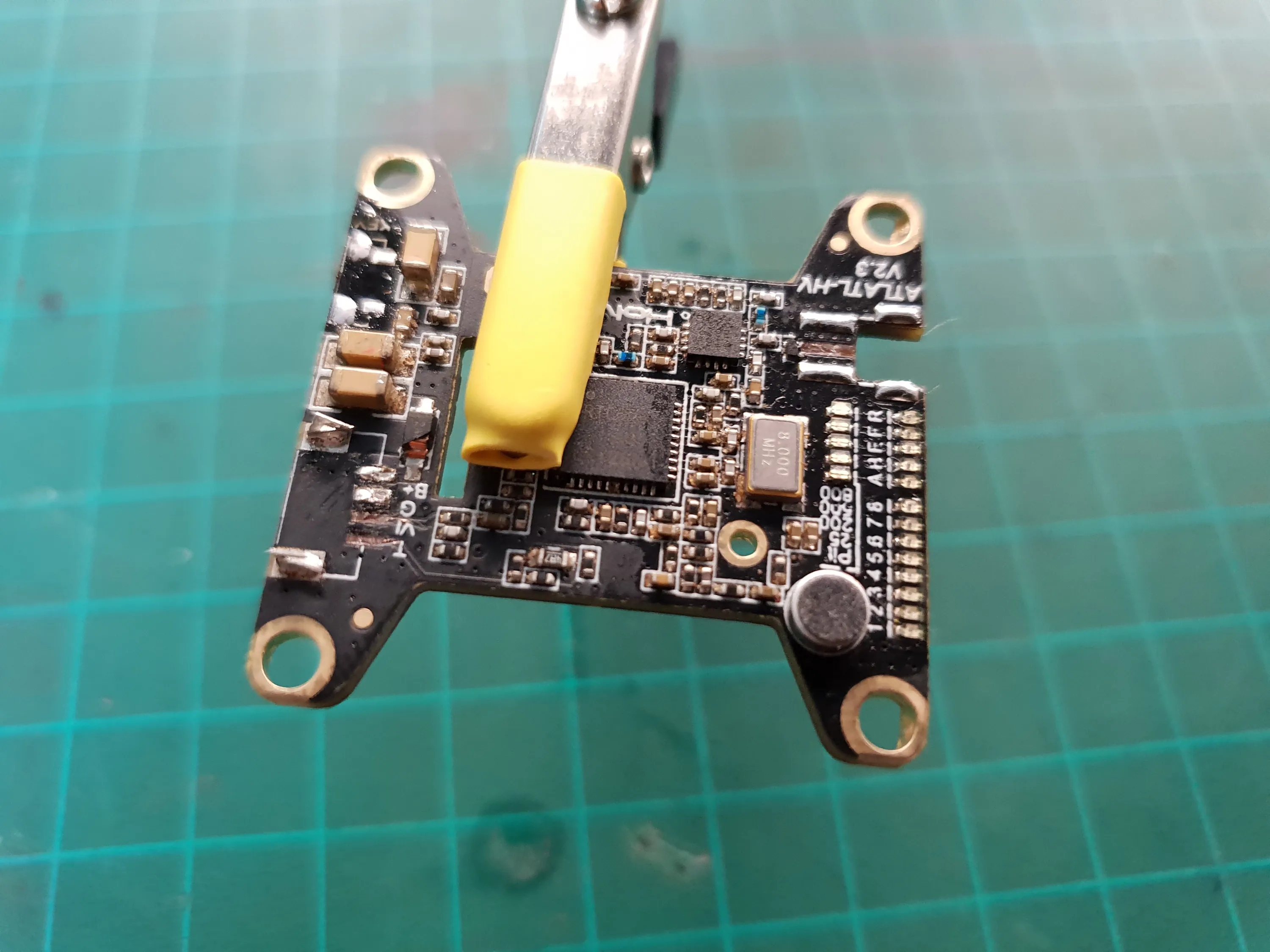
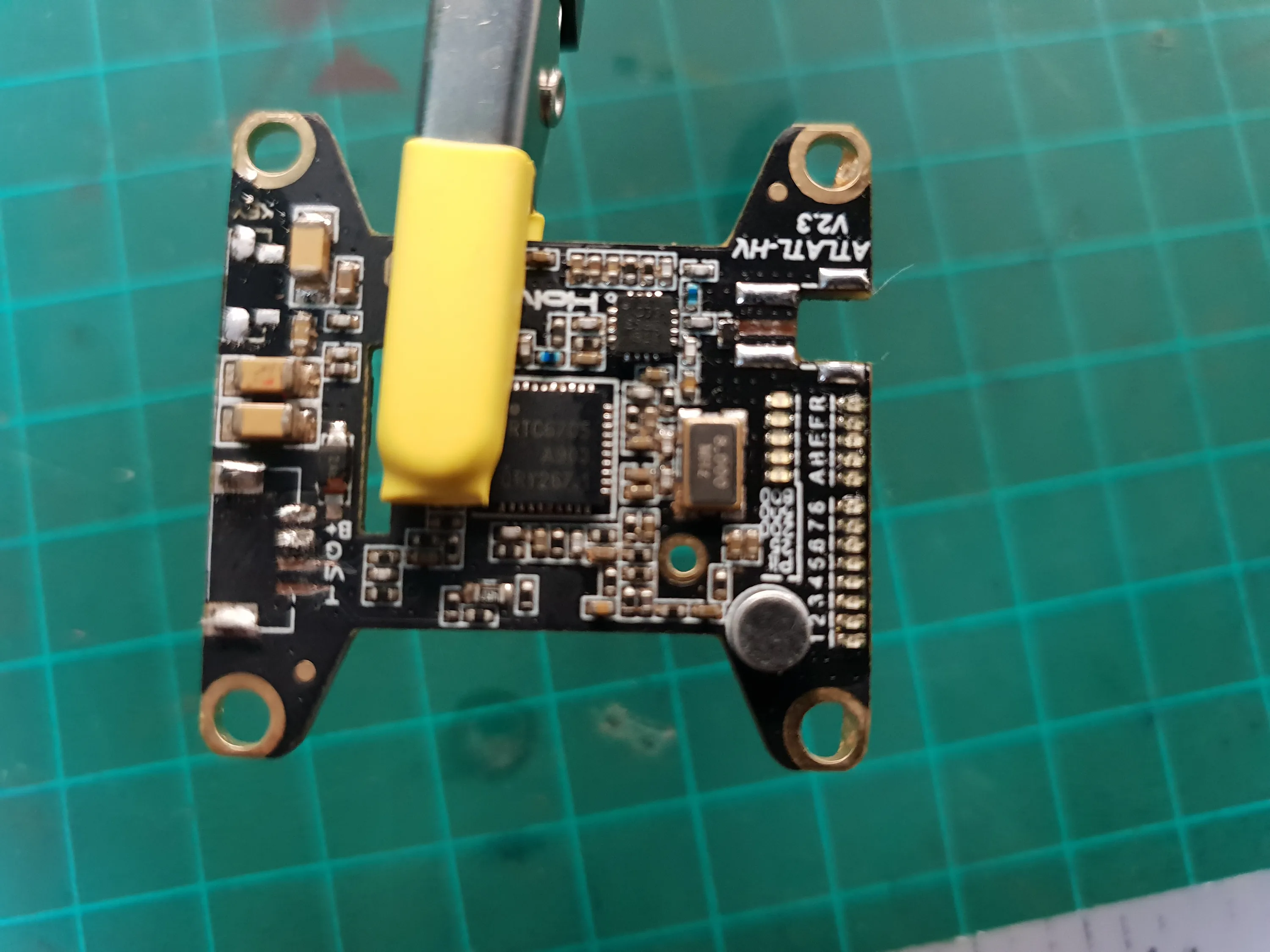
A friend of mine crashed his quadcopter pretty hard and broke multiple parts. In this article I’ll be looking at his VTX and trying to fix it.
Diagnosis
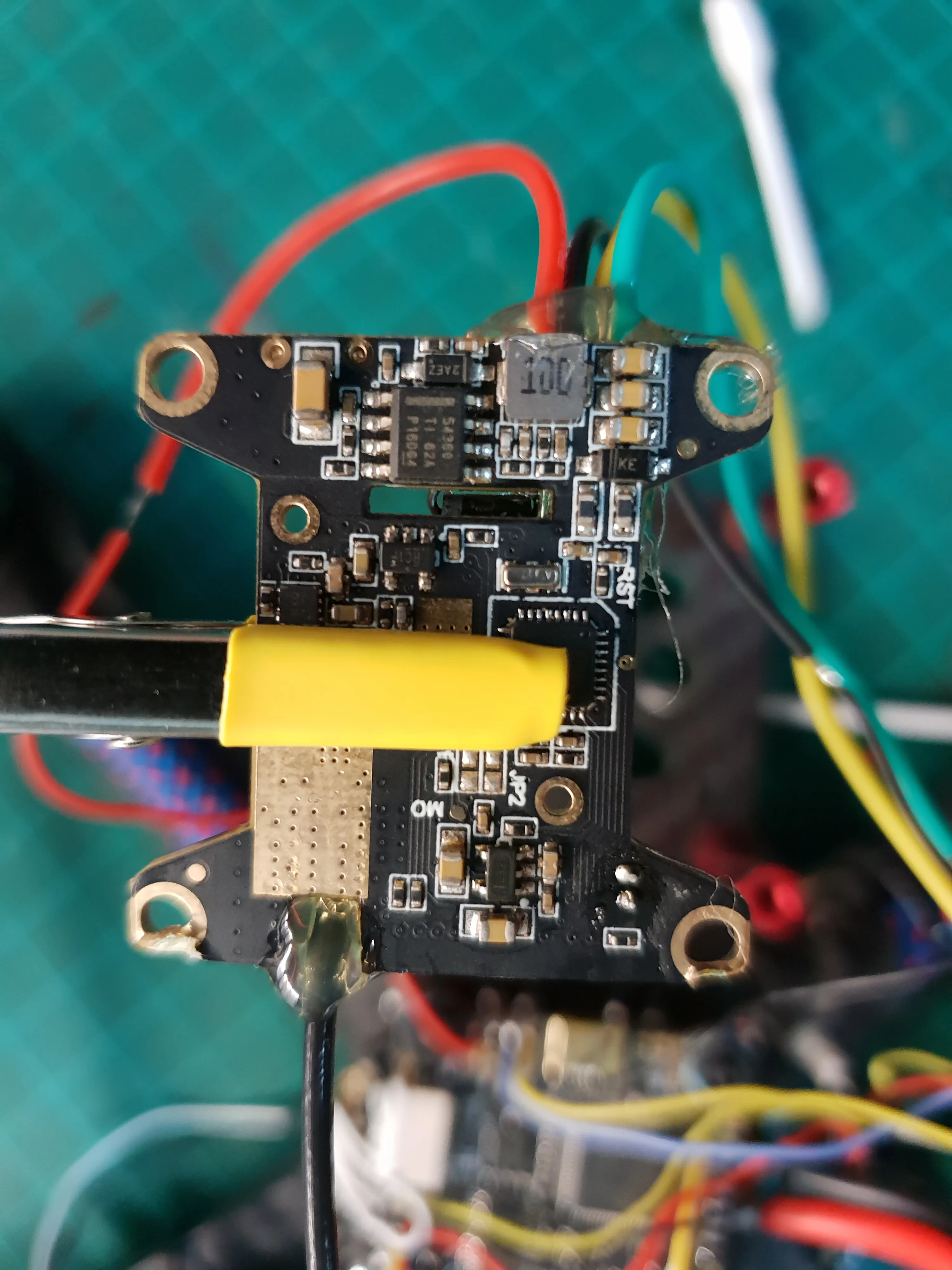
Powering the VTX up will give more information about what’s wrong, but from looking at it, I can see that the MMCX antenna connector was ripped off, so I won’t be powering it up until that’s fixed as it may damage the receiver.
I can also see that the connector to the flight controller and the button are broken (both already removed in the photos).
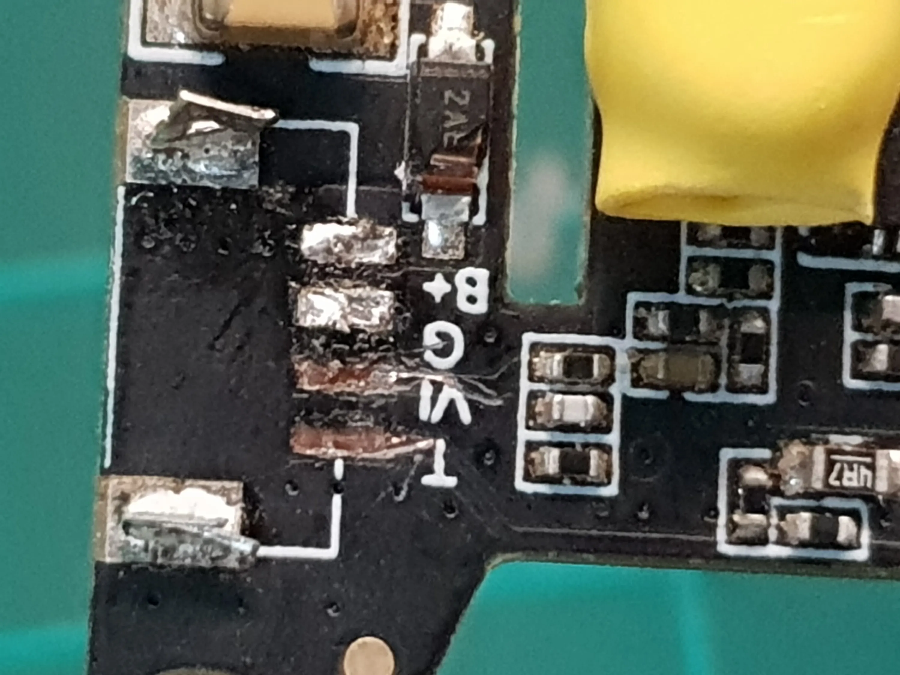
There’s also a diode near the power input pins that seems to have a cracked package.
Attaching an Antenna
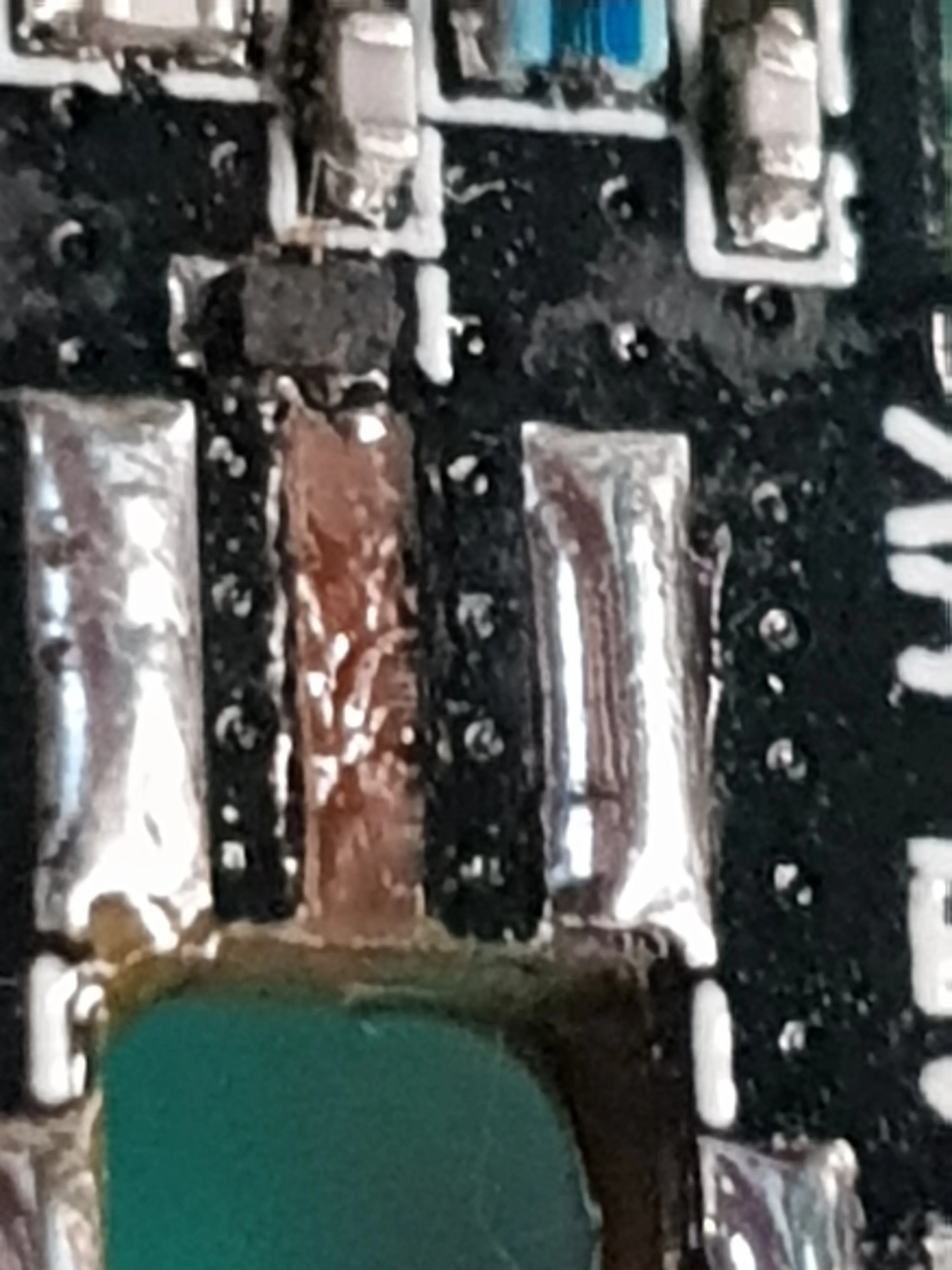
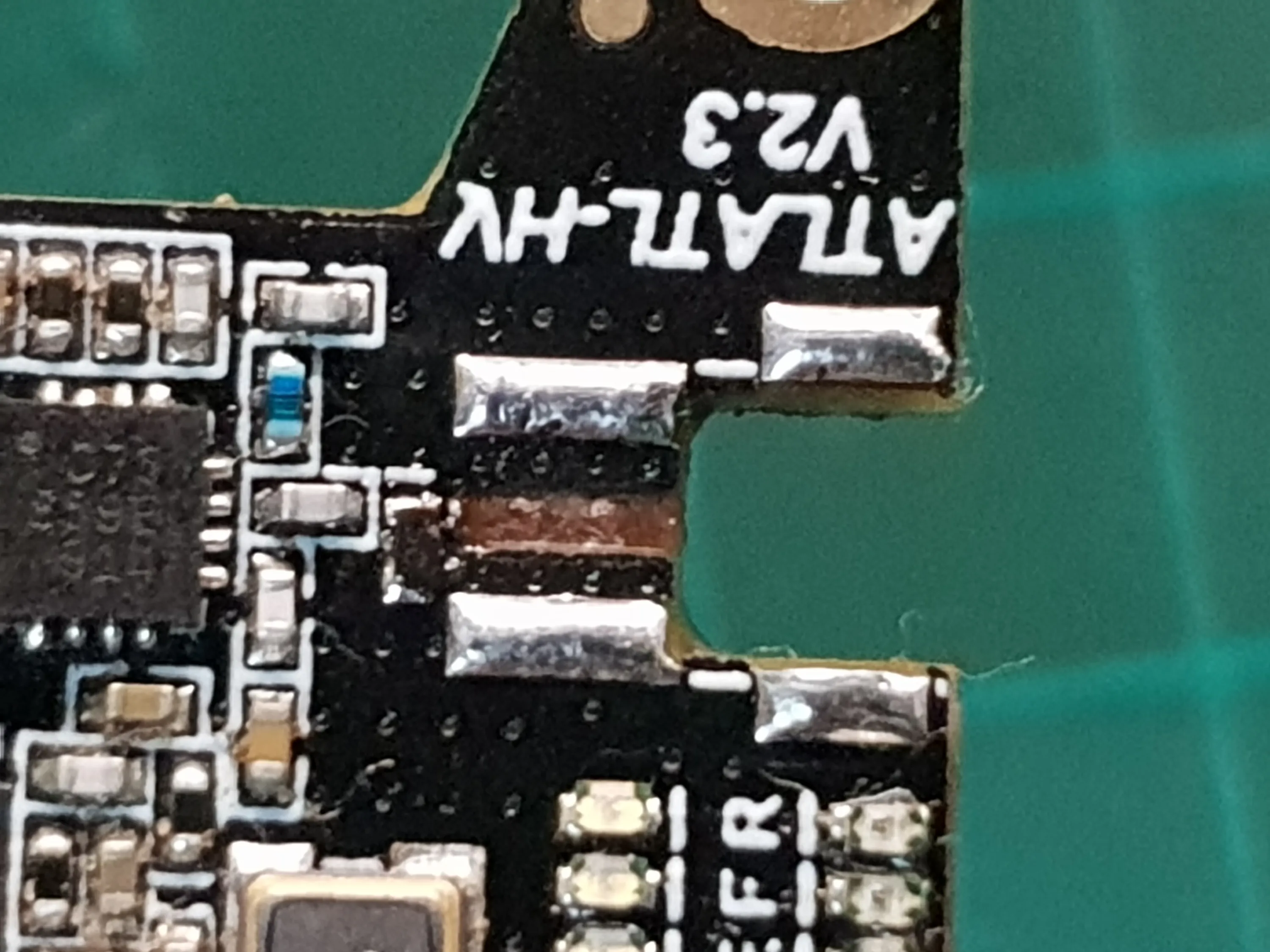
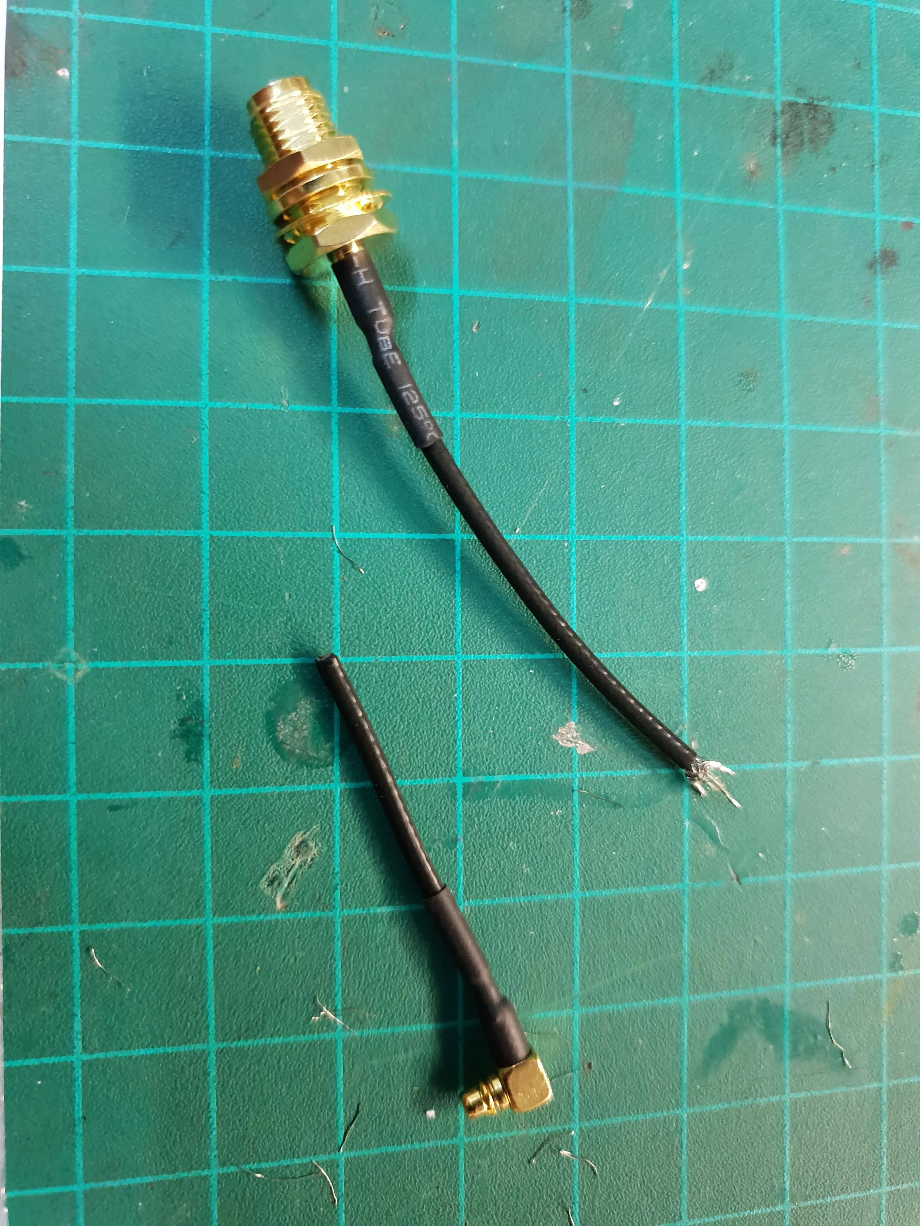
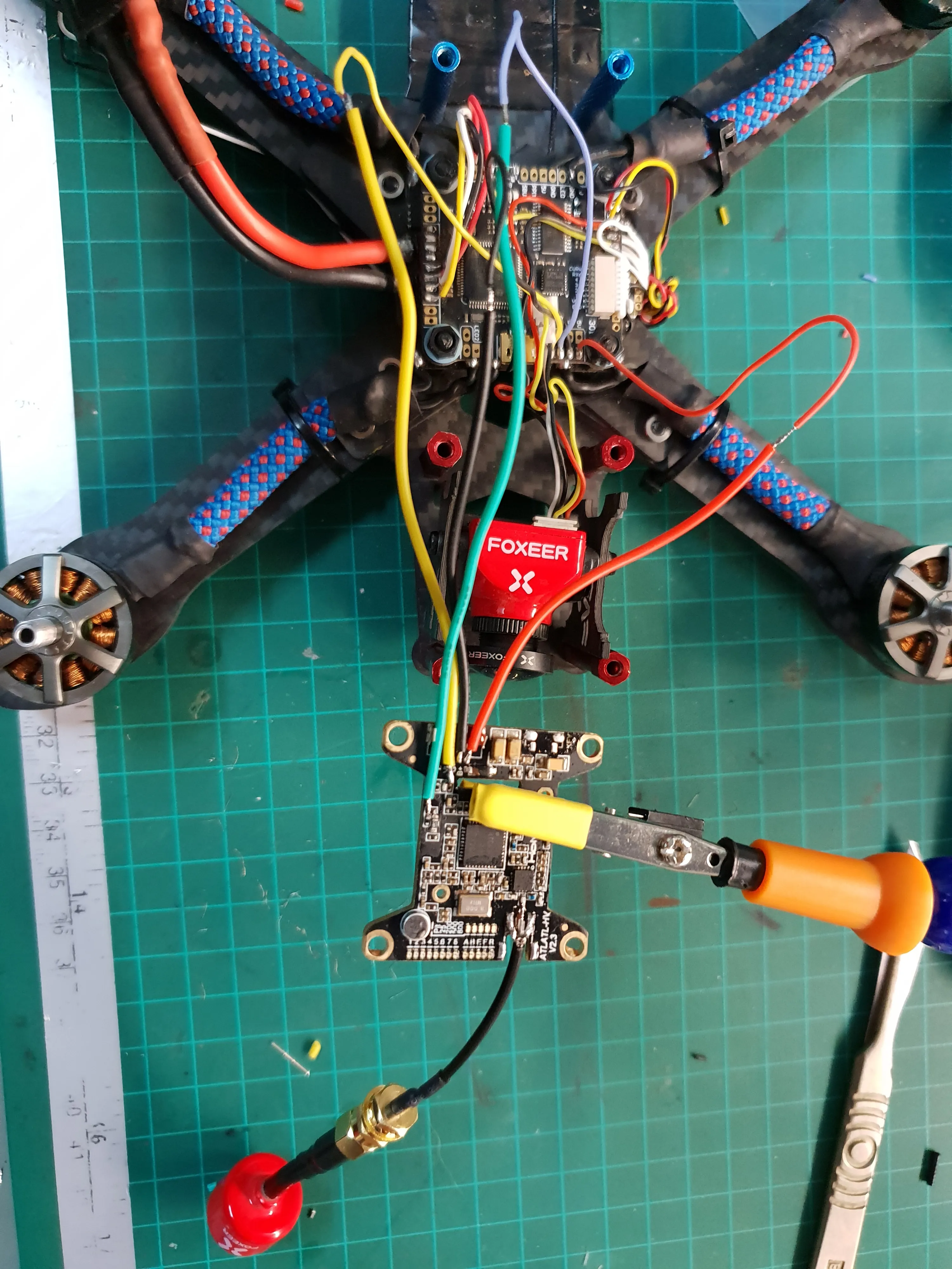
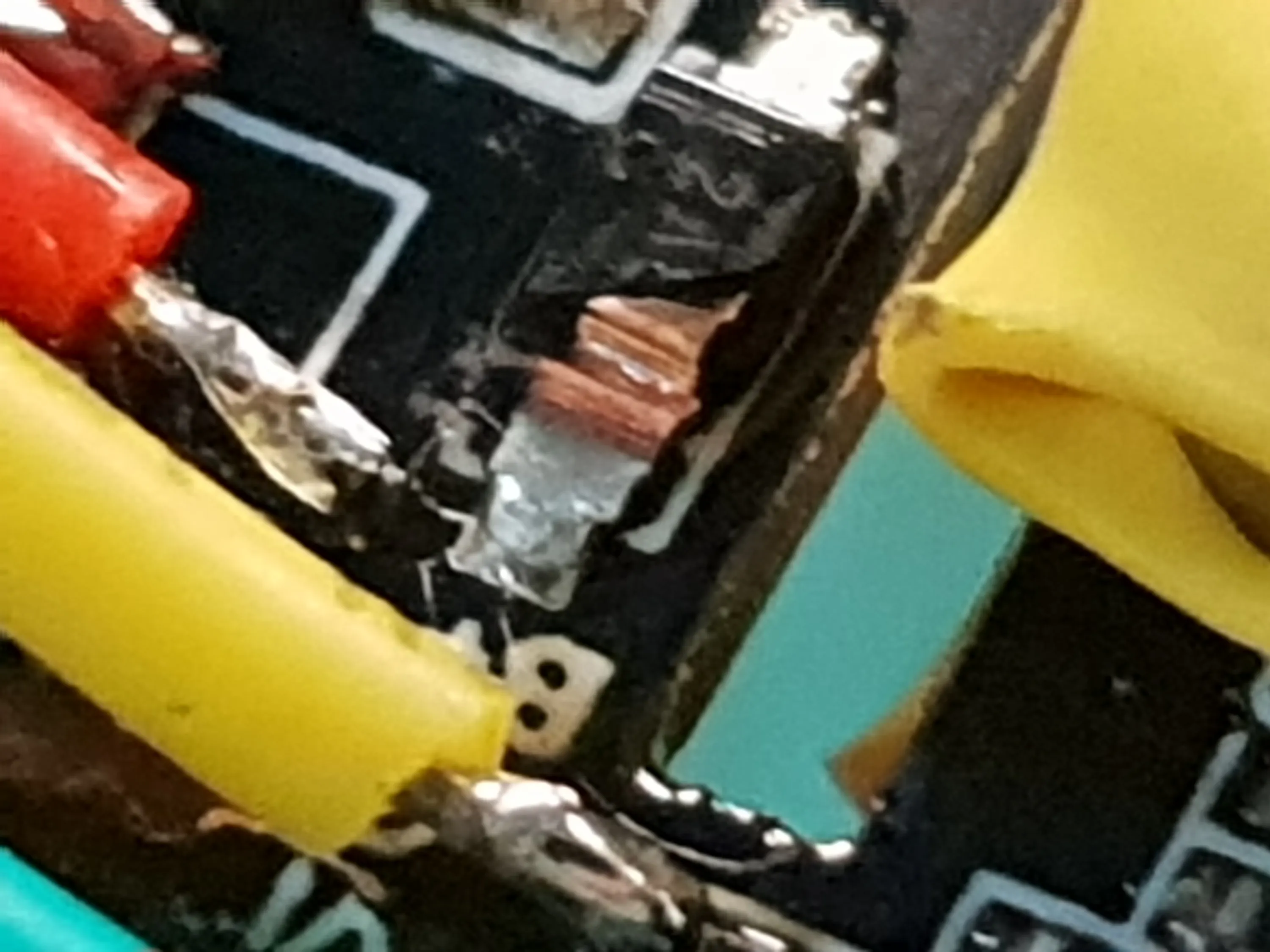
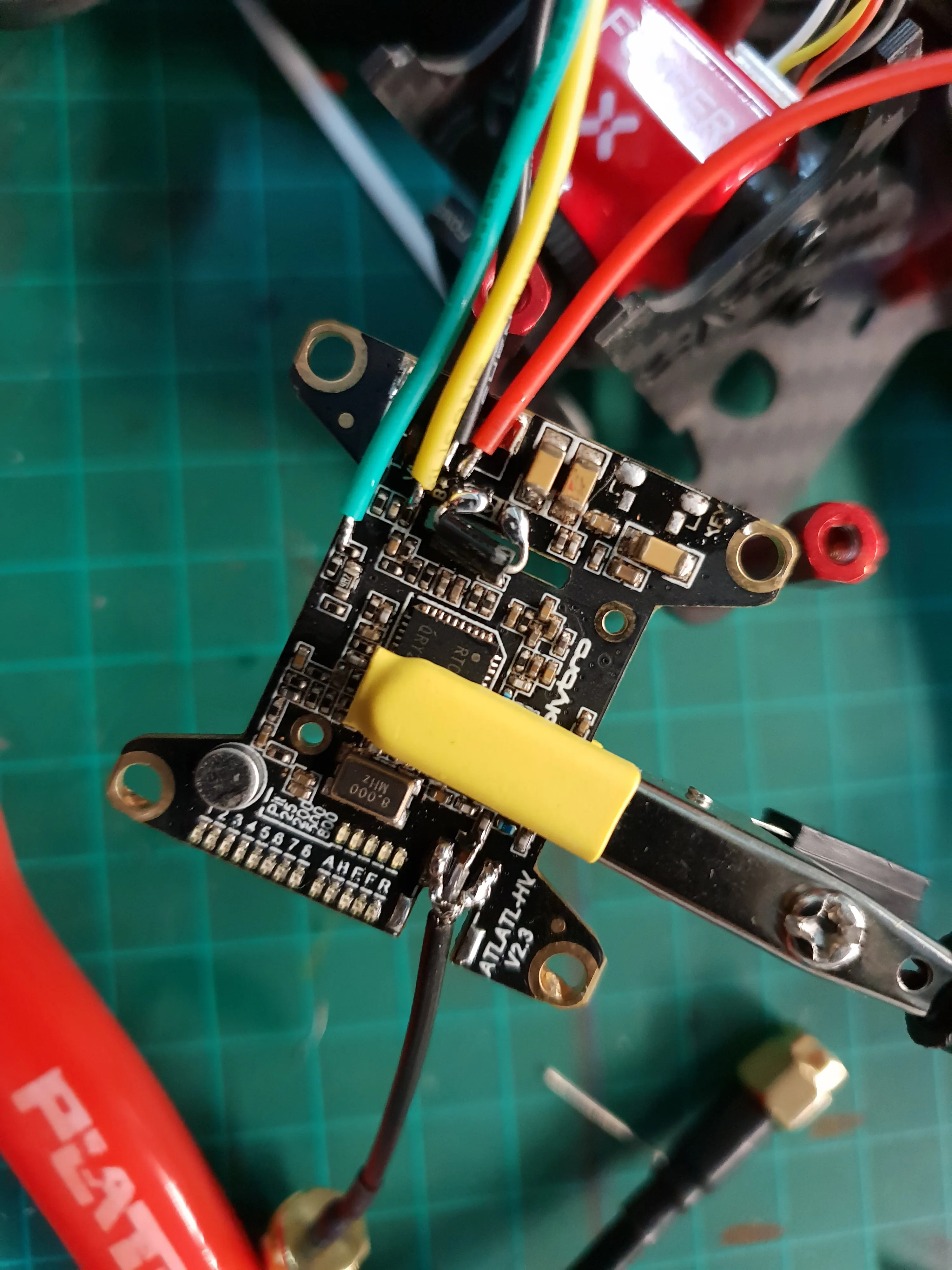
The connector itself was never found after the crash and I don’t have spares of this kind, so I decided to butcher a coax pigtail and solder it straight to the board.
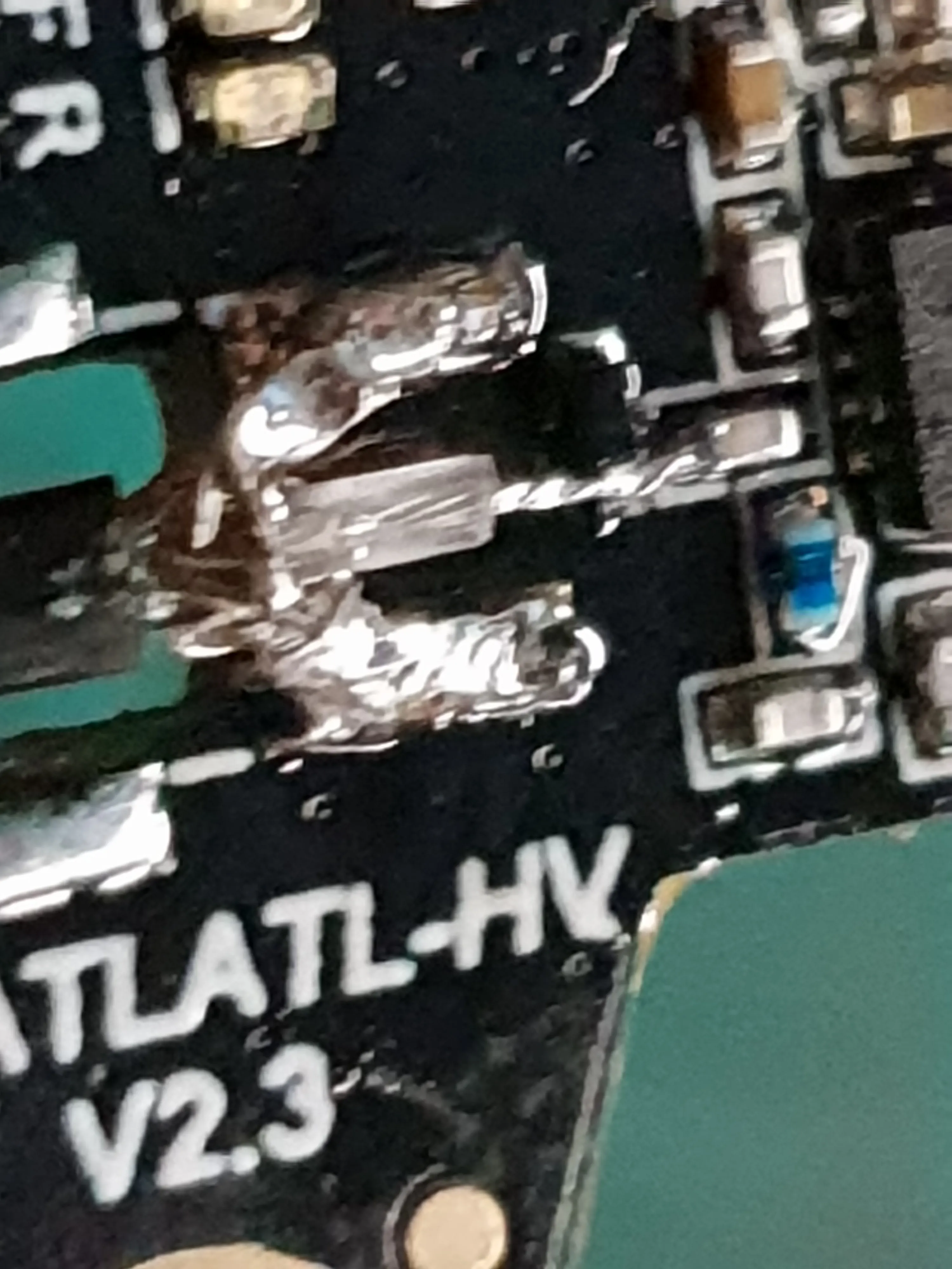
Further inspection of the place for the connector reveals that the signal pad is also ripped from the board.Moreover, the designers of the board put a diode very close to the pad itself, leaving no extra trace to which to solder, so I would have to solder to the diode itself.
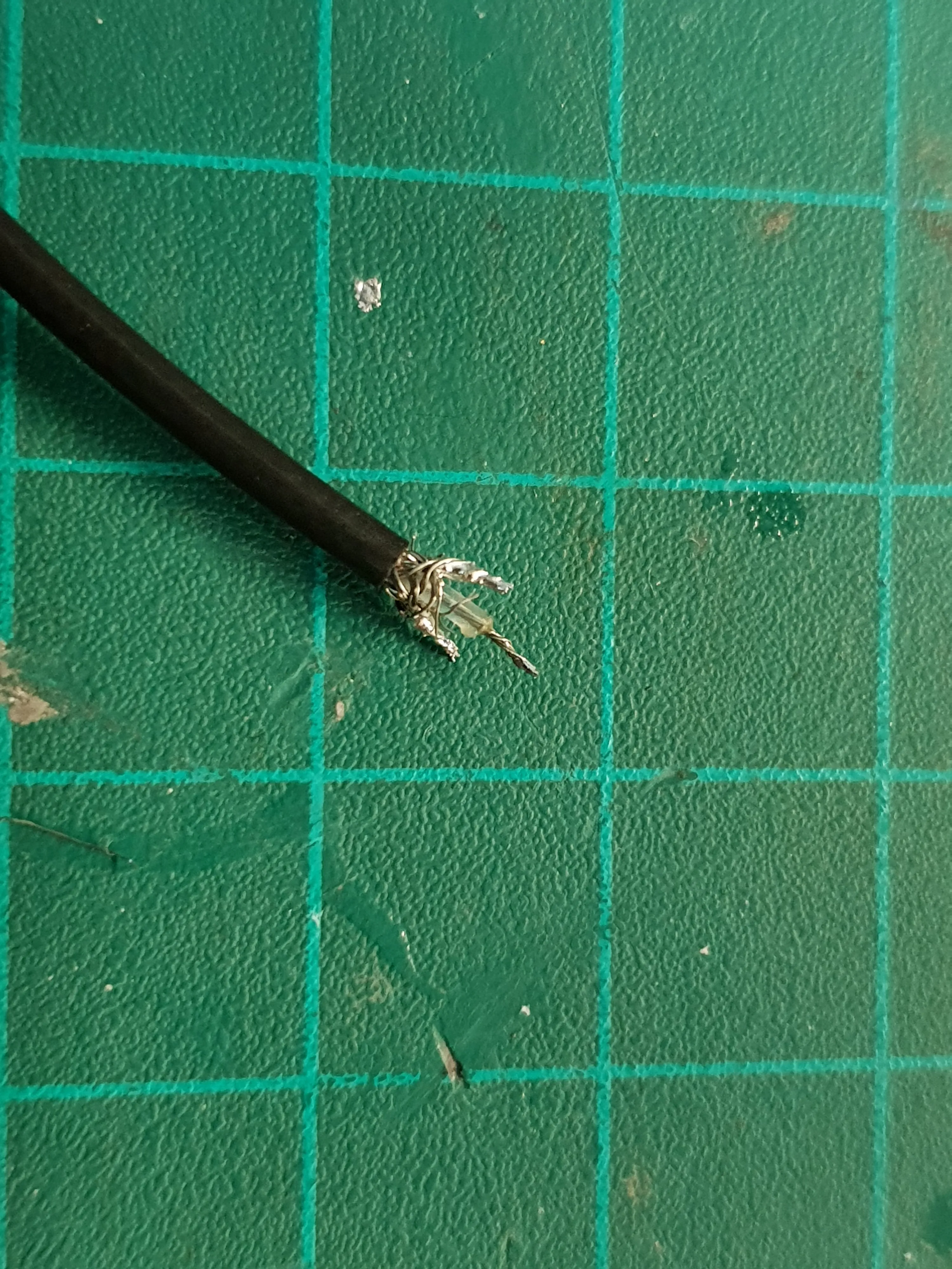
I took a pigtail and carefully peeled the outer insulation, without cutting the shielding. Then I exposed the center wire and shaped the shielding to fit the pads on the board.
The Connector
Now that the antenna is connected, I can power the device, but there’s no way to feed it power or video, since the connector is broken.
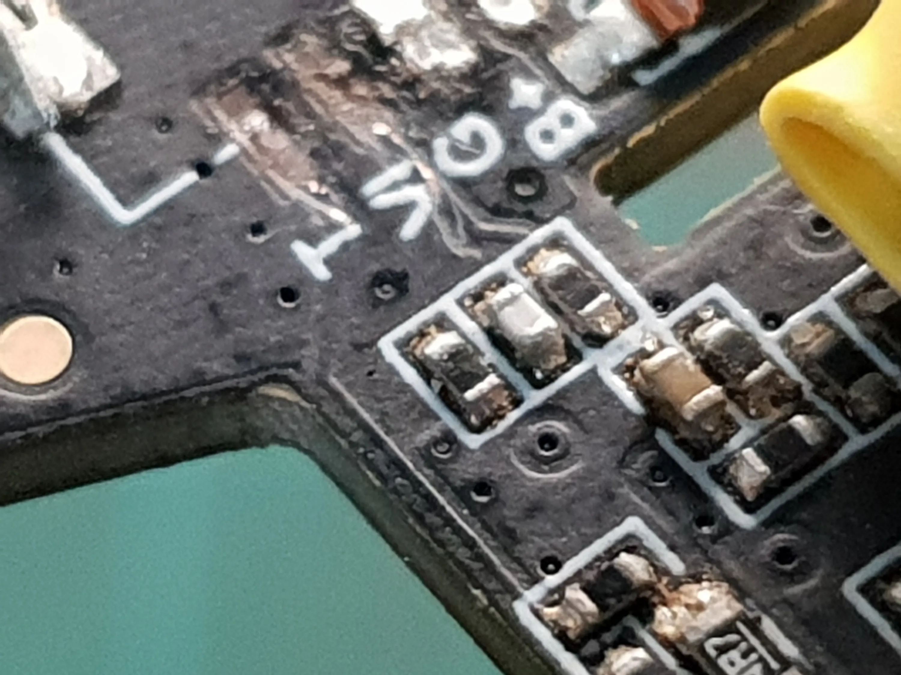
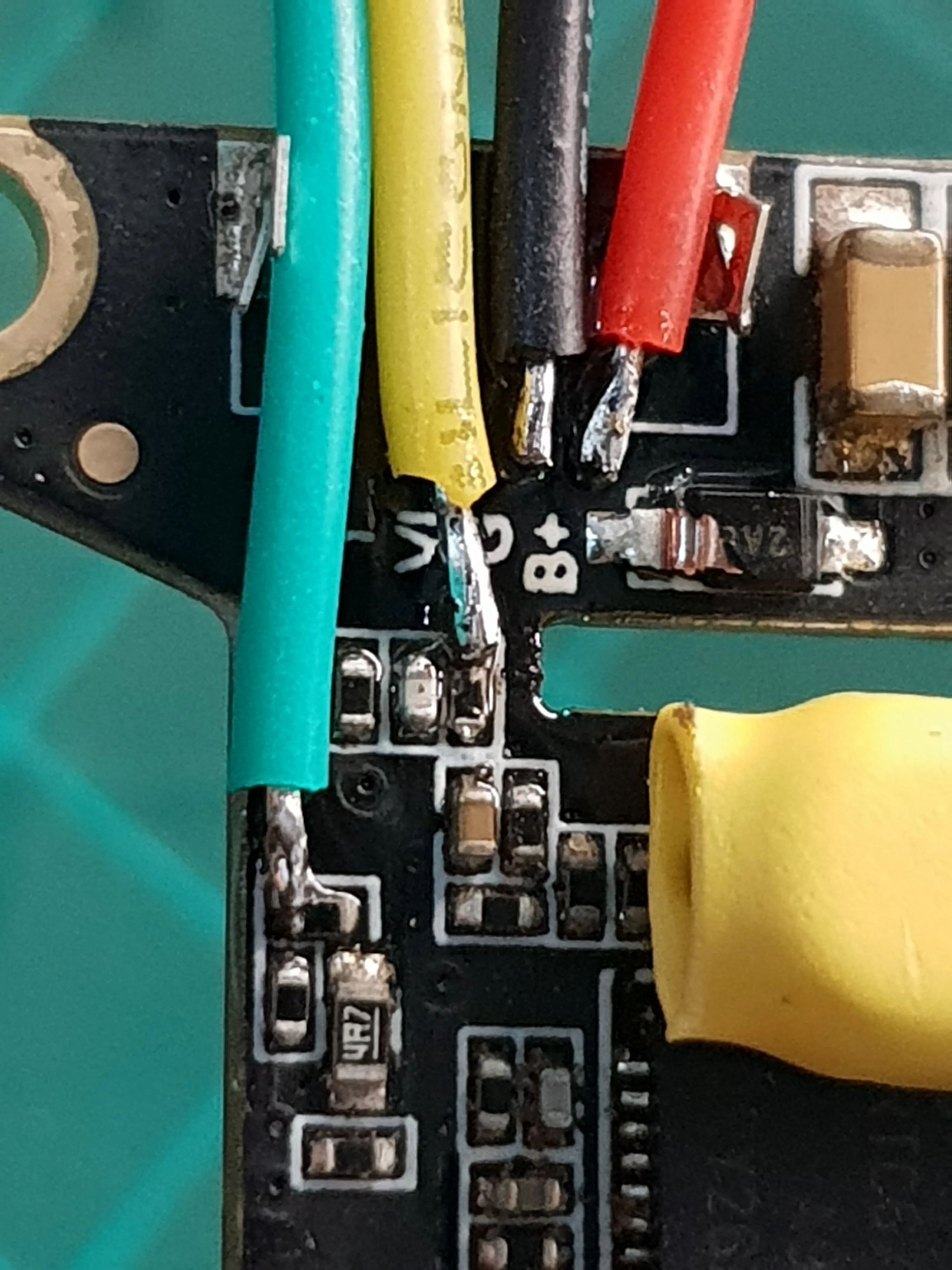
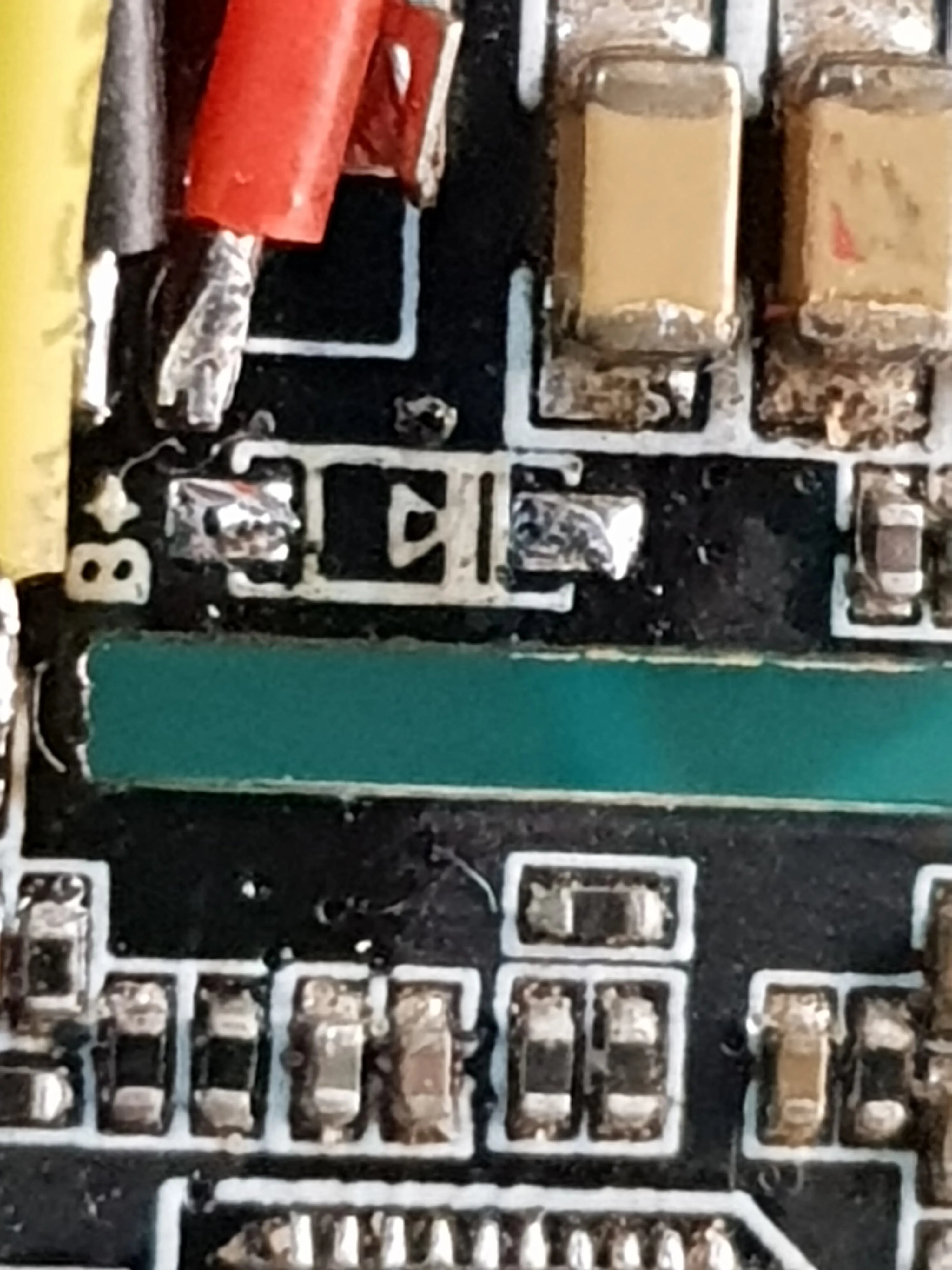
A closer look at the connector pads shows that the video input and the smart audio port’s pads are missing.I followed the traces visually to see where they go on the board and then scraped some of the solder mask to expose the copper trace and check the continuity to the components I reached.
Powering Up
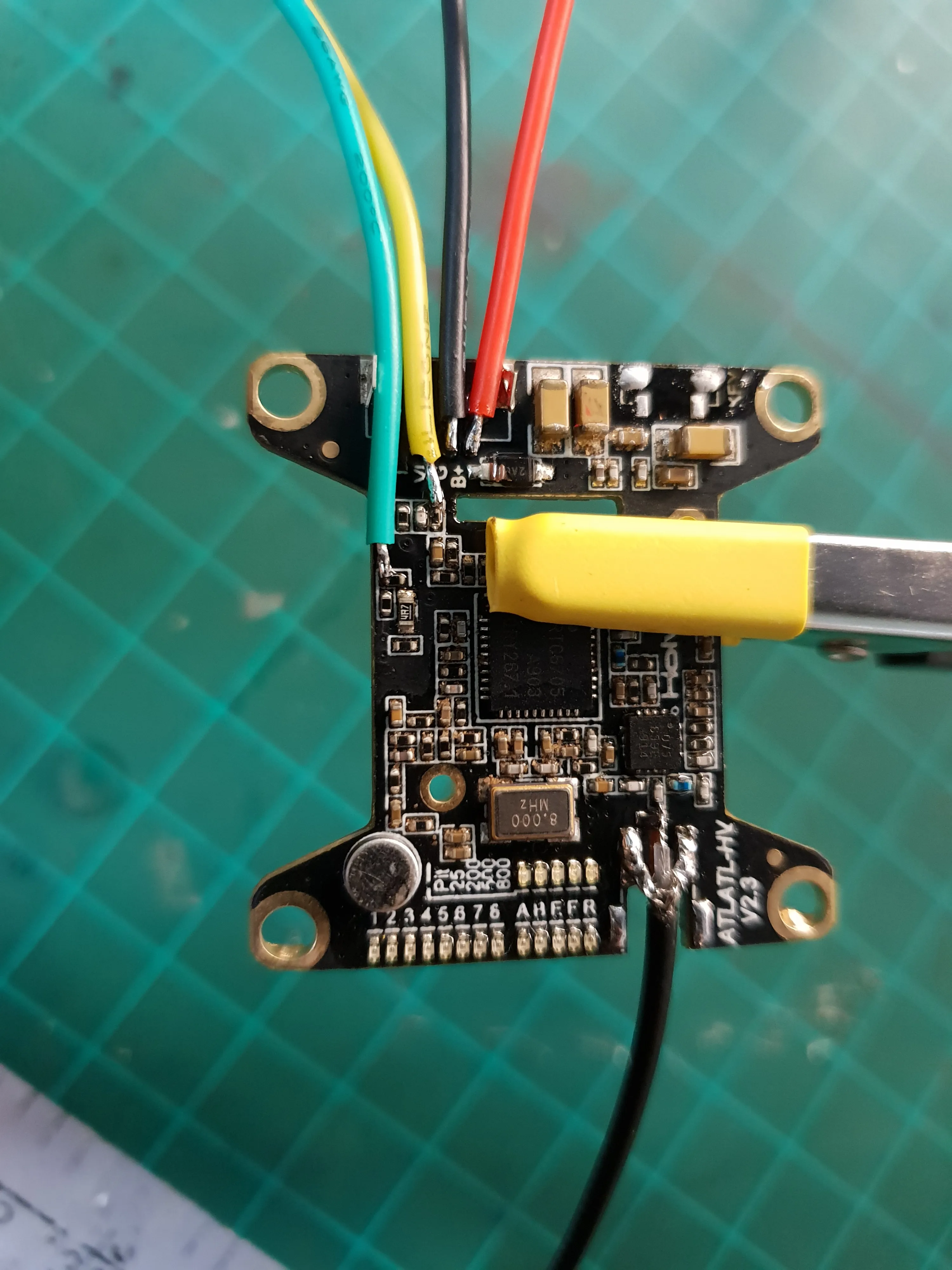
After connecting wires to the available pads and to the components to which the ripped pads lead, I powered the device to get more information.
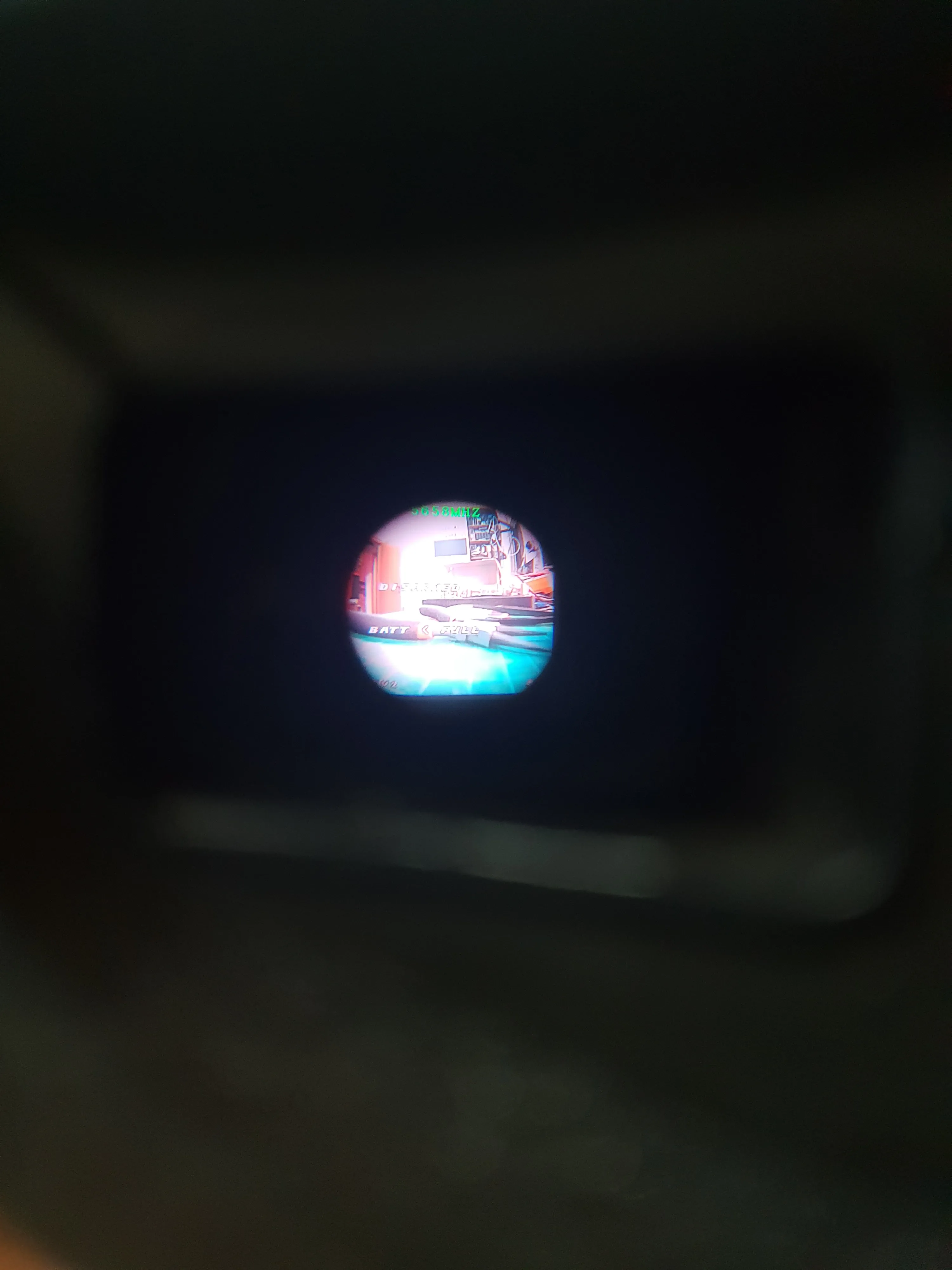
The device powers, I can see the indication LEDs and I can feel it getting warm.Viewing the signal in my FPV goggles, reveals static noise and occasional distorted and dark image.
This means that the VTX is getting power, stepping it down correctly and it’s controller is working.This also means that the busted diode either still works or it’s there for protection and isn’t strictly needed for operation. I think it’s the latter.
Wiggling the antenna around doesn’t seem to do anything, but wiggling the video input cable changes what’s received by my goggles and for a fraction of a second gave me a clear image.This gives me hope and means that the problem is probably not with the transmitter itself nor the antenna.
Replacing the Diode
I wanted to eliminate any other parts that may affect the operation of the device, so I decided to replace the diode before continuing.
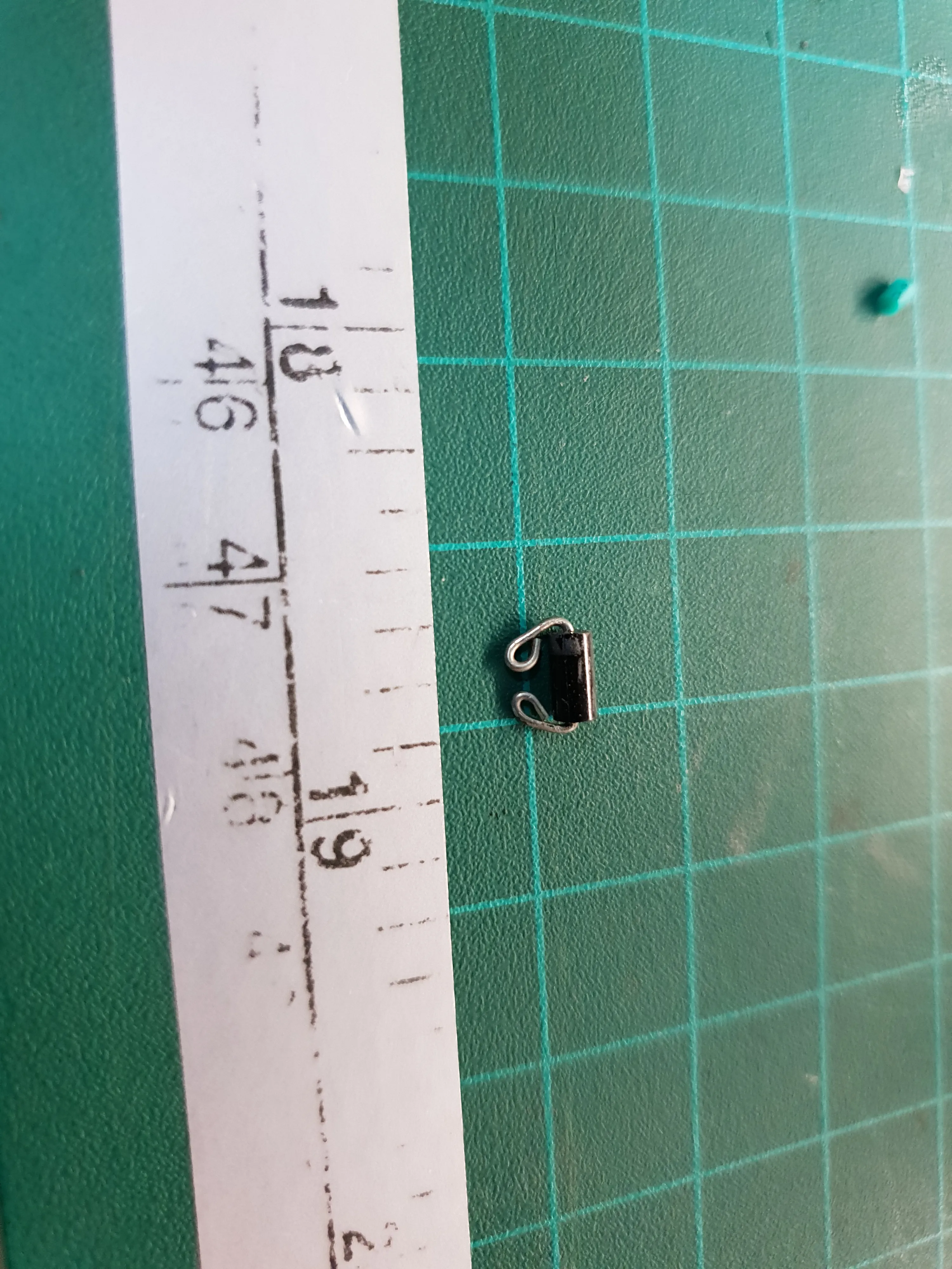
I tried figuring out the exact part number of the diode to research it’s parameters, but half of the package was gone and all the photos I found online were not clear enough. I could only make out the “2A” at the beginning.
Since this is probably a protection diode, It’s parameters shouldn’t matter much. it just needs to be able to take the battery voltage. A simple 1N4007 sould do nicely.
I folded the new diode’s leads to fit the pads and soldered it in place.
Another power up and check with the goggles showed no change.
Better Contact
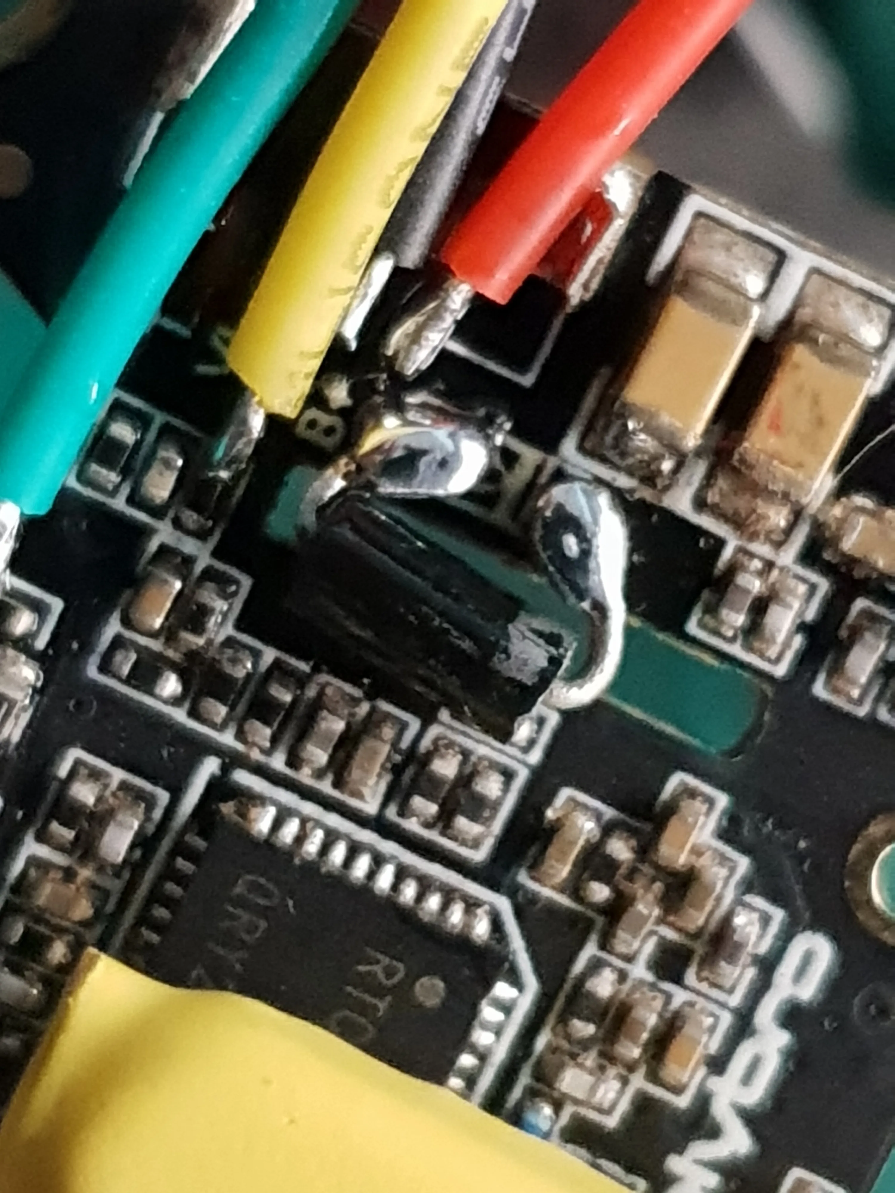
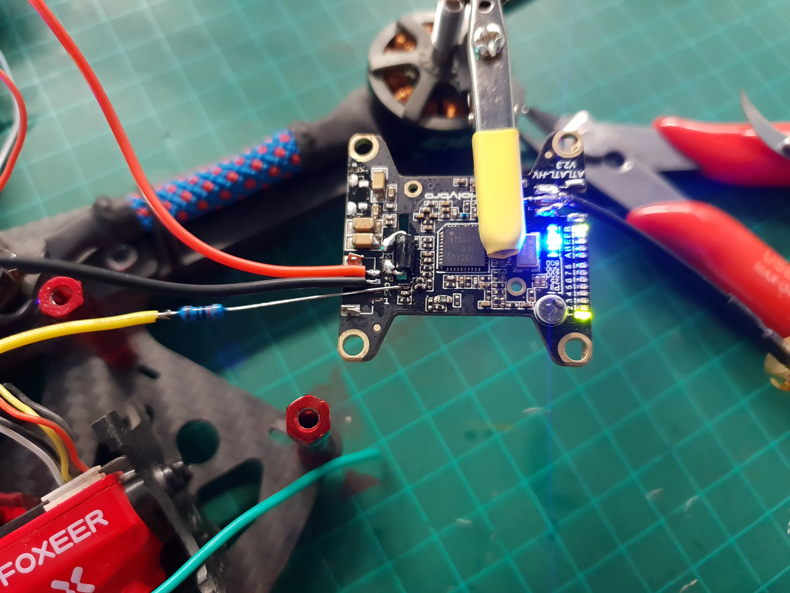
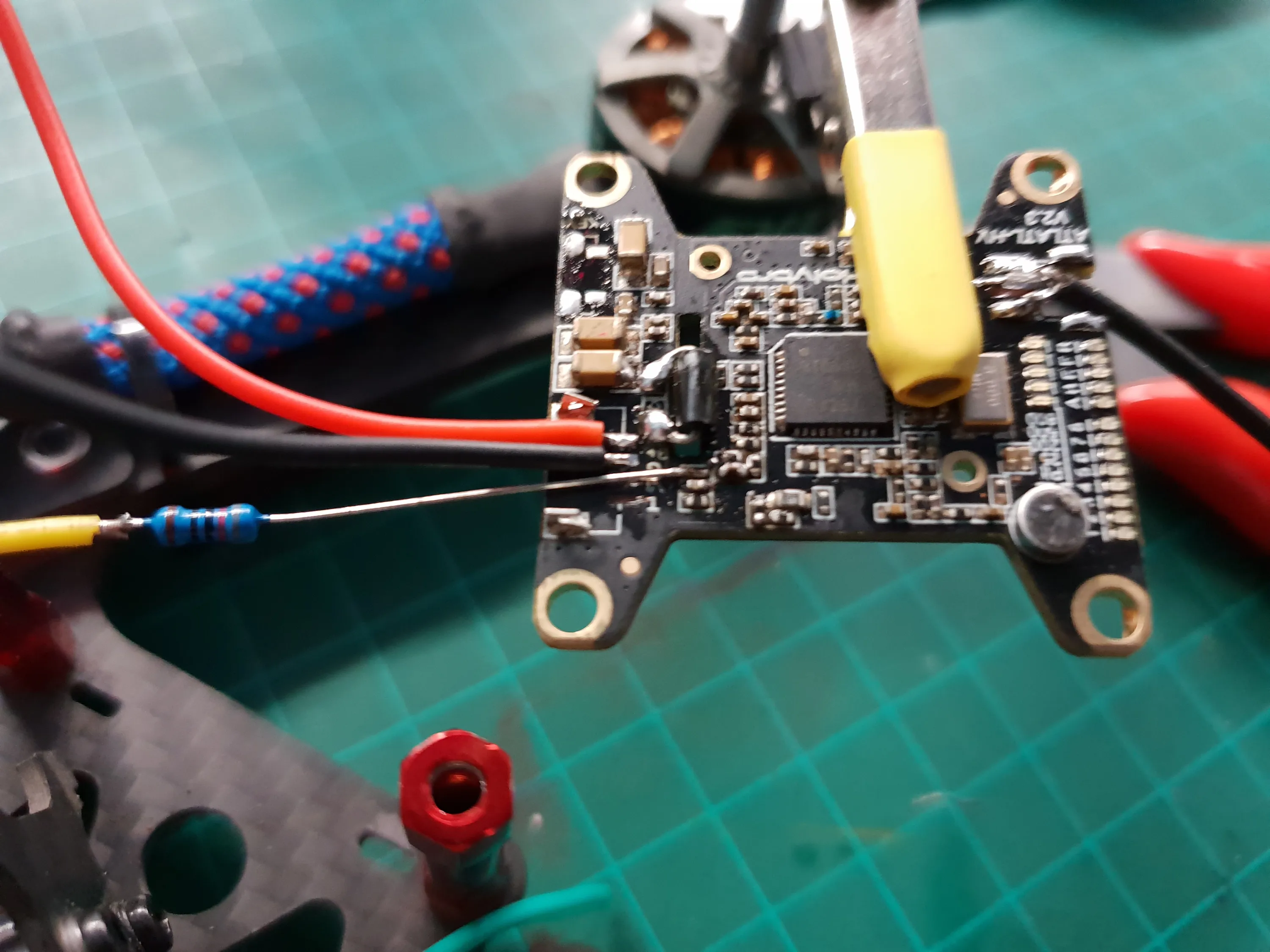
Initially, I soldered the video input wire to the resistor to which the trace leads, but the resistor is very small and the solder joint is very weak and breaks easily.
I tried finding another spot that connects to the same side of the resistor, but didn’t find one. I measured the resistor to see if it’s damaged, bit it was fine and measured around 750 Ohm. I decided to replace it with one that would be easier to solder.
Replacing the resistor wasn’t easy as the pads are very small, but I managed to use both pads together to give a strong enough bond (this didn’t matter electrically that the pads were shirted because one side of the resistor only went to the connector pad which is no longer connected to anything)
Ditching the Button
The button on this model of VTX is not used for configuration, like it is in many others, but for a special boot mode.
My friend said he never uses the button and when I said I’ll have to replace it with something much bigger that will have to be mounted somewhere else, we agreed to remove it and leave it out.
Any configuration can be done via Smart Audio anyway.
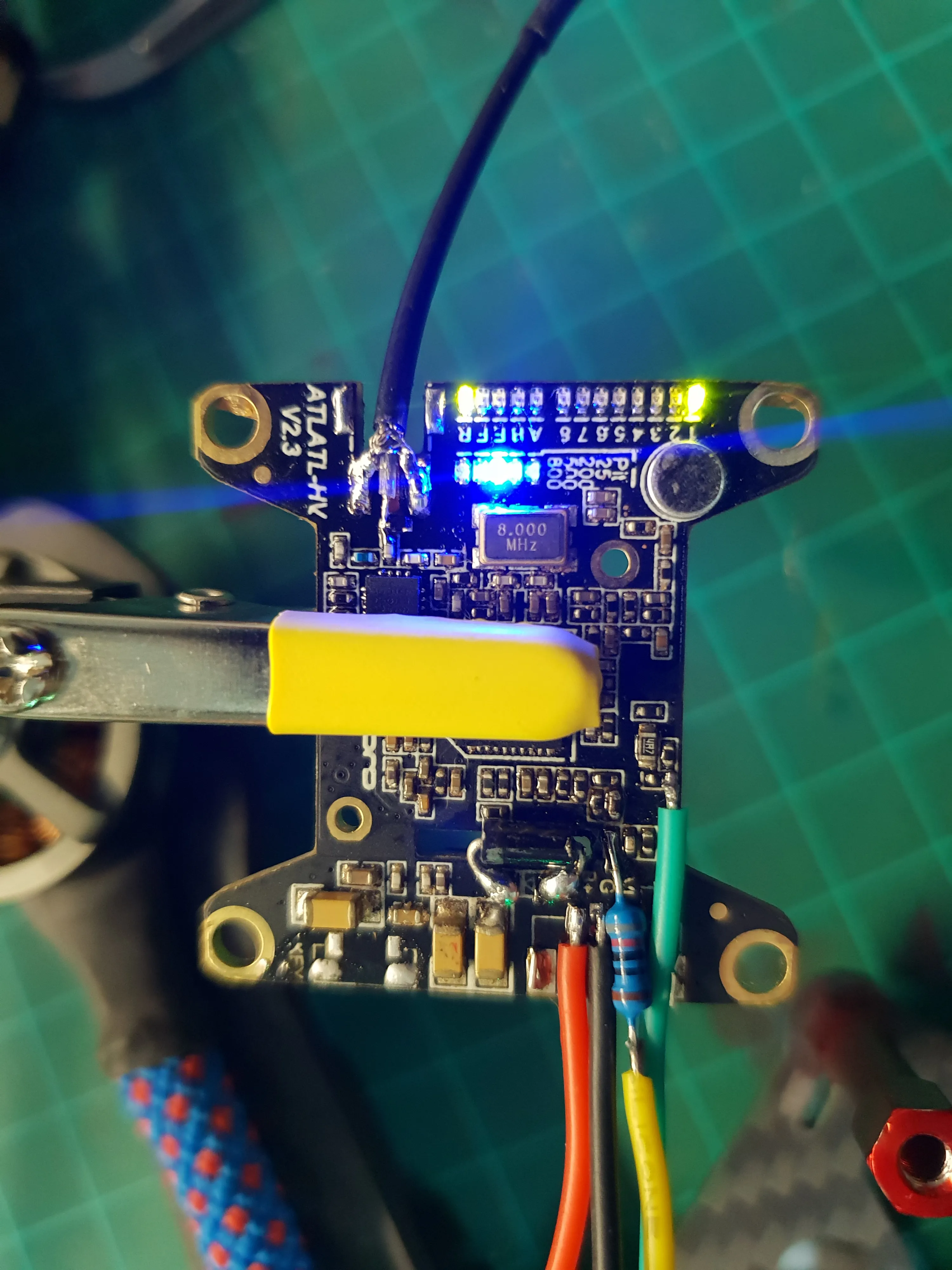
Success!
It works!
After connecting all the wires securely and powering up again, I can see a clear image in my goggles. The problem was fixed.
Reinforcement
The antenna’s solder joints aren’t very strong and the antenna wire will move a lot with the motion and vibrations of the drone and when plugging and unplugging the antenna from the connector.
The soldered wires at the connector pads also have small solder joints that will break it pulled too hard.
To help with strain relief and vibration protection, I used hot glue hold the wires in place.
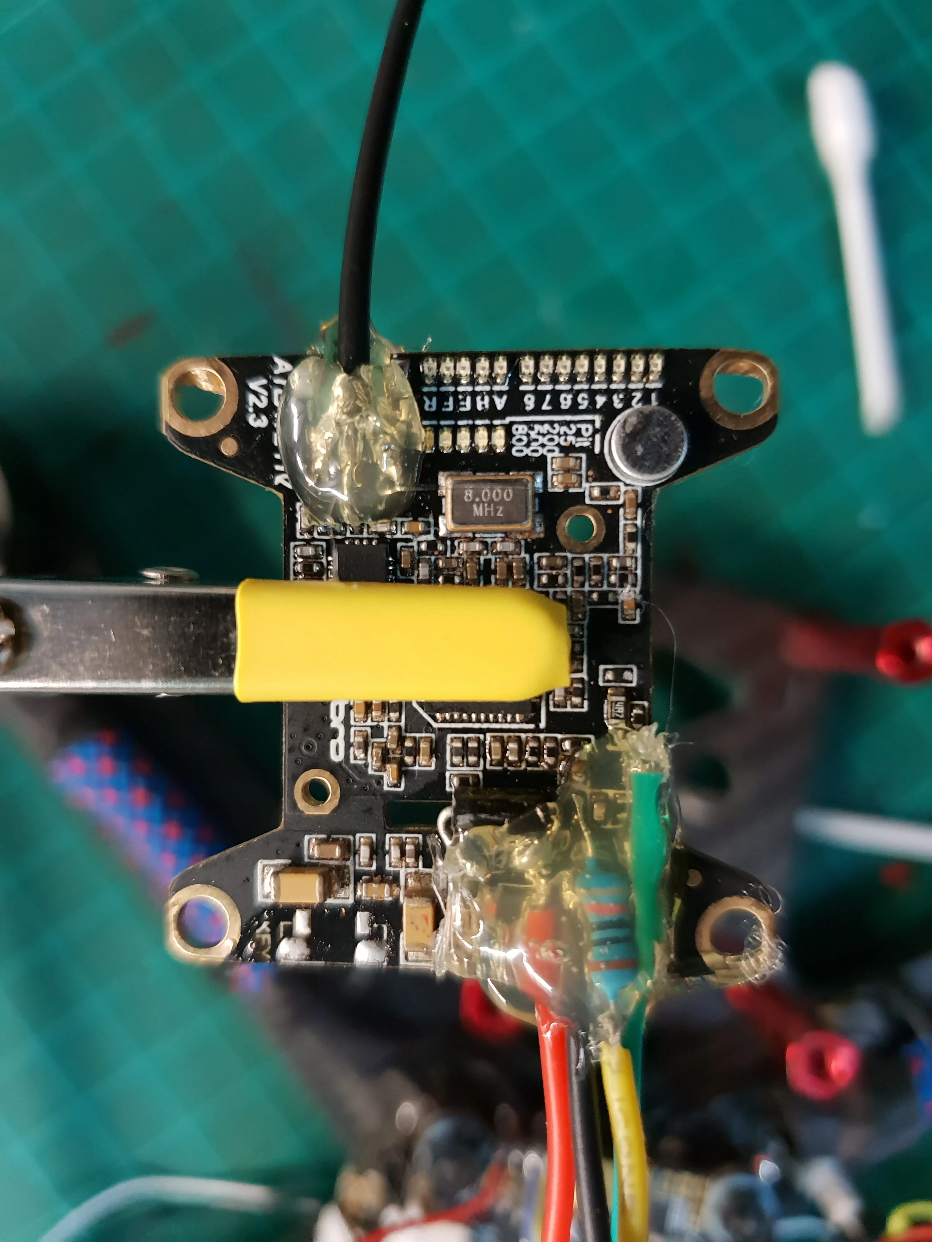
It’s not very pretty, but it will get the drone in the air until a replacement VTX arrives.