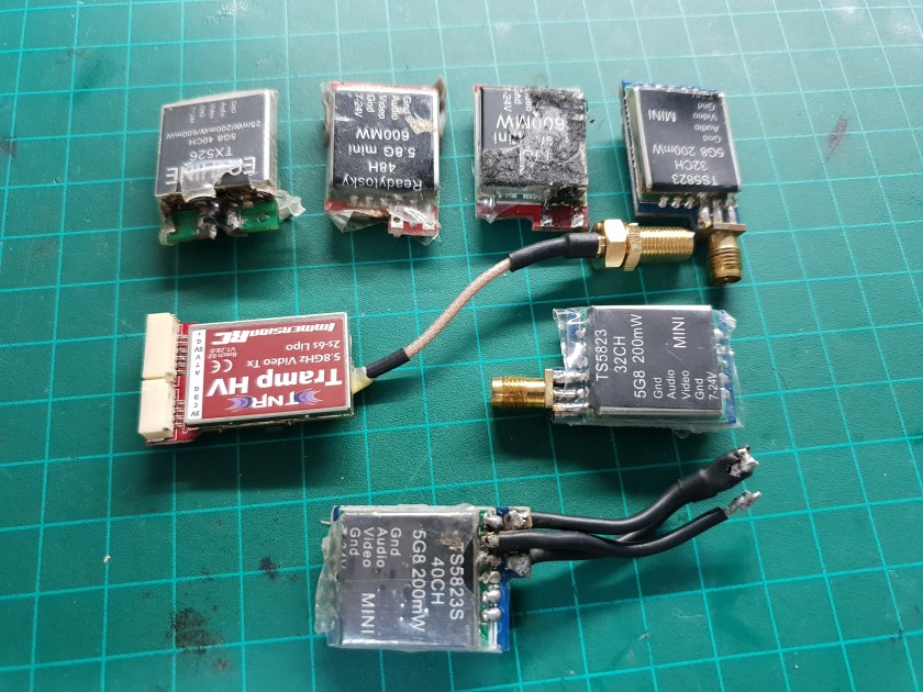
I got a box of old and defective VTX’s. Let’s see if anything is salvageable.
VTX #1 – Tramp HV
This is a relatively new VTX. It stopped working immediately after a not-so-hard crash.
Diagnosis
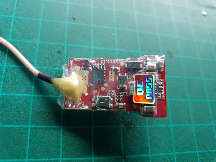
Physically, it looks great. There doesn’t seem to be any obvious damage.
Powering up regularly
plugging it in to power doesn’t do anything, no LEDs whatsoever and the transmitter doesn’t heat up.
This usually means something is wrong with the power supply.
Injecting power
The transmitter itself is powered by 5V regulated on-board.
To bypass the power supply section and see if anything else is wrong, I connected 5V from a current limited power supply to the output of the on-board power supply (this is usually on the opposite side of the largest inductor on the board).
I turned the power on and sure enough, the LEDs light up and I can feel the transmitter warming up.
We have power, but do we have video?
I connected a camera to the video input and turned my FPV gogggles on to view the signal.
The video looks great.
This means that the only problem was the on-board power supply.

Making It Fly-Ready
I don’t have replacement parts for this power supply, and the flight controller on any drone already has a 5V regulator for powering various peripherals.
My idea is to bypass the on-board power supply the same way I did in the diagnosis, but with 5V from the flight controller.
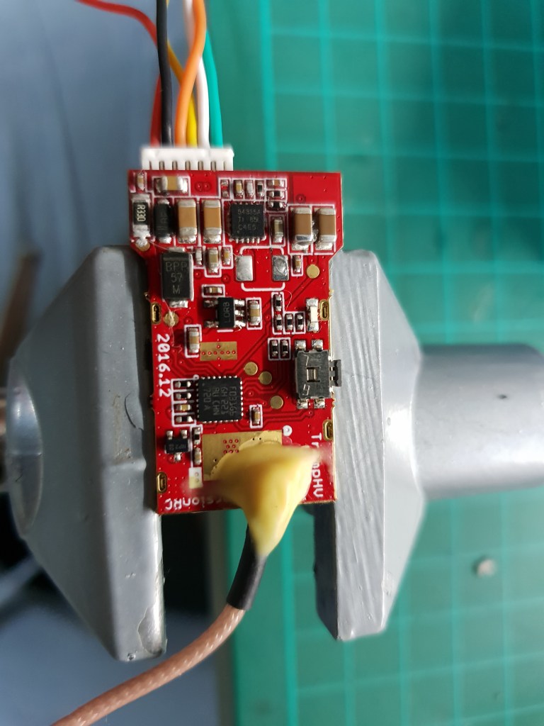
If we look closely at the connector of the VTX, there’s a 5V output pin that is meant for powering the camera from the VTX’s power supply.
Following it with a continuity meter on the board reveals that it’s connected straight to the output of the power supply, after the big inductor – the same place I injected the voltage before.
This means that I can use the 5V output as an input instead of soldering another wire to the board.
Making It Safe
Back feeding the power supply isn’t a good idea. Especially when I’m not sure what is wrong with it.
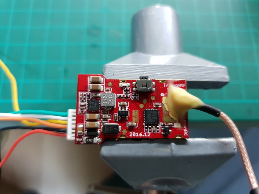
To prevent any additional damage, I want to separate the output pin from the power supply.
Usually, the inductor is in series to the power supply output, meaning that if it’s removed, the power supply is isolated and not connected to anything.
A check with a continuity meter confirms that the power supply doesn’t connect anywhere else and everything that gets power gets it from the other side of the inductor.
I removed the inductor and tested again with power on the 5V output pin.
Everything works fine.
How To Use It Now?
Usually, you would power the VTX straight from battery voltage to the power input pins and the camera from either battery voltage (if it supports it) or from 5V from the flight controller or the VTX.
Now, the VTX has to be powered with 5V from the flight controller to the 5V output pin, leaving the power input pin disconnected.
As for the camera, if it was powered via battery voltage or from the flight controller, there isn’t any change.
If it was powered from the VTX, it would need to be powered by something else.
Physically, the camera can be connected to the same pin for power, but electrically, the power will come from the flight controller and not the VTX power supply.
VTX #2 – Eachine TX526

Diagnosis
This VTX seem to have been repaired before. It seems that the antenna connector was broken and replaced with a cable (which also broke?)
The under side of the VTX looks fine. I don’t see any burnt or damaged components.
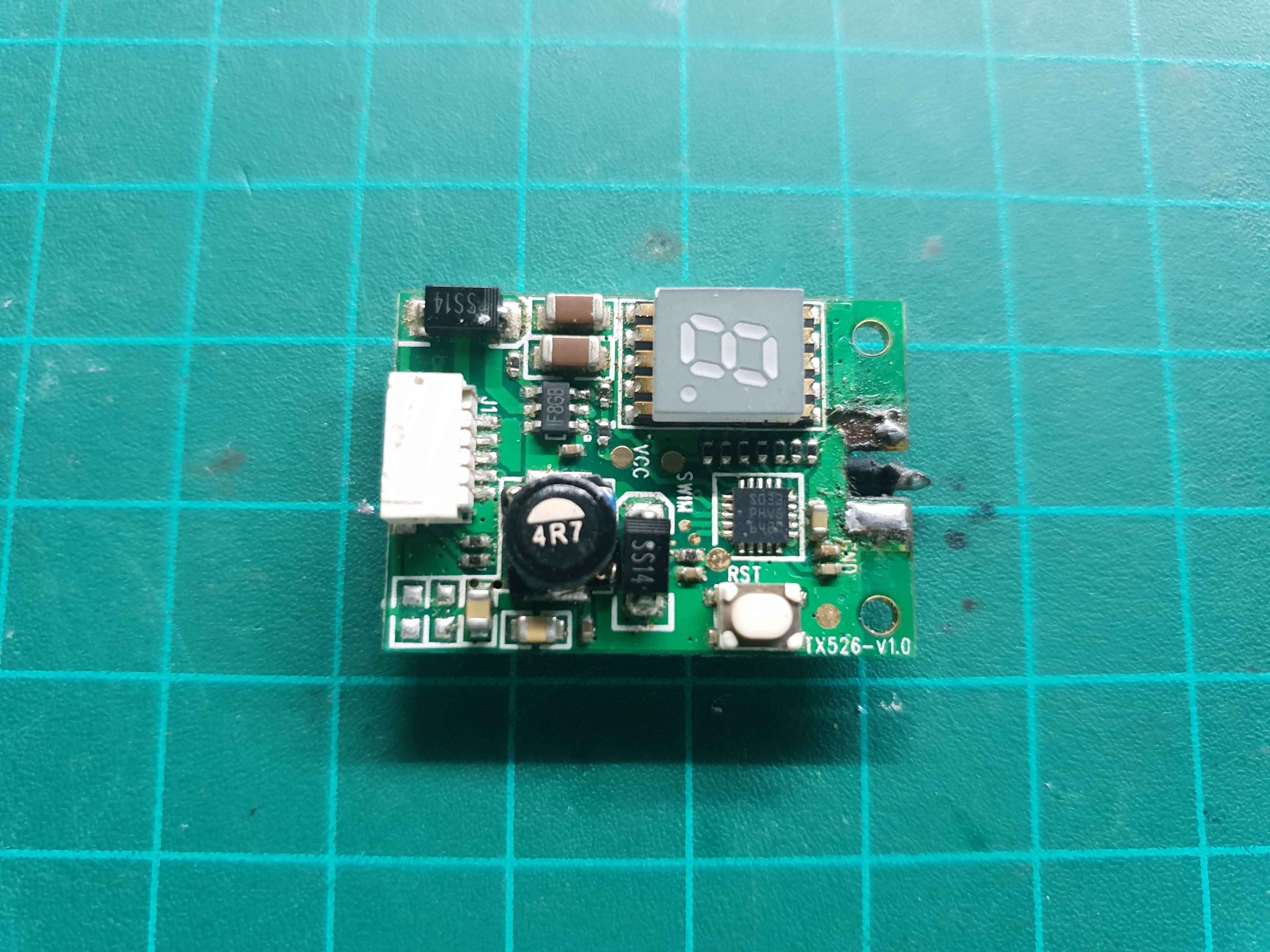
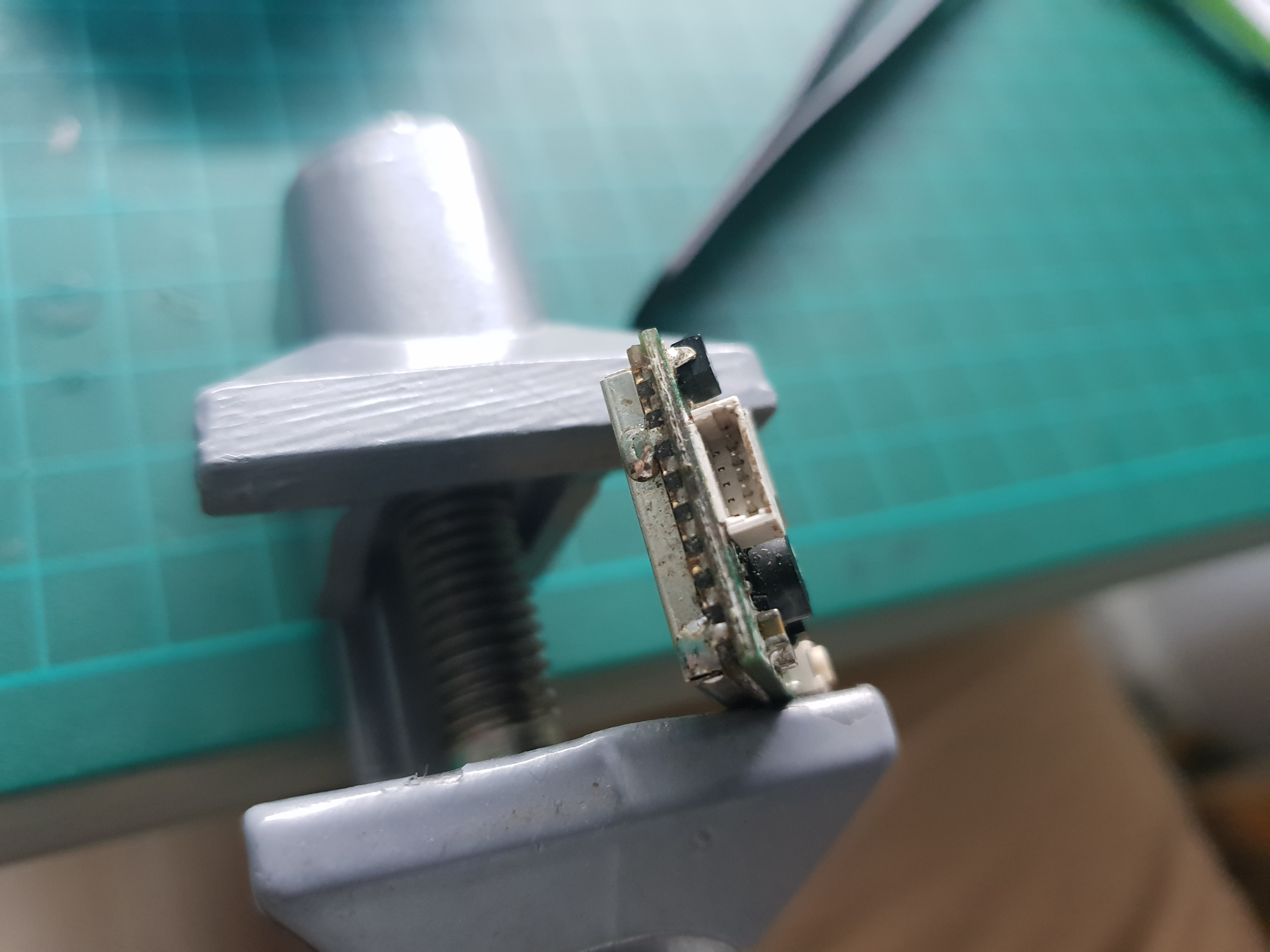
The connector itself looks fine, but it has a bent pin.
Powering up a transmitter without an antenna may damage it, so any further diagnosis will be made after an antenna is connected.
Fixing The Antenna
I took a (broken) SMA antenna connector that came with the box of VTX’s and soldered it in place as best I could, as some of the pads on the board were ripped and some of the legs of the connector were broken.


Straightening The Pin
This one is very simple. I just took a thin and pointy pair of tweezers and carefully bent the pin back.
This has to be done slowly and carefully to not break the pin, making the whole connector useless.
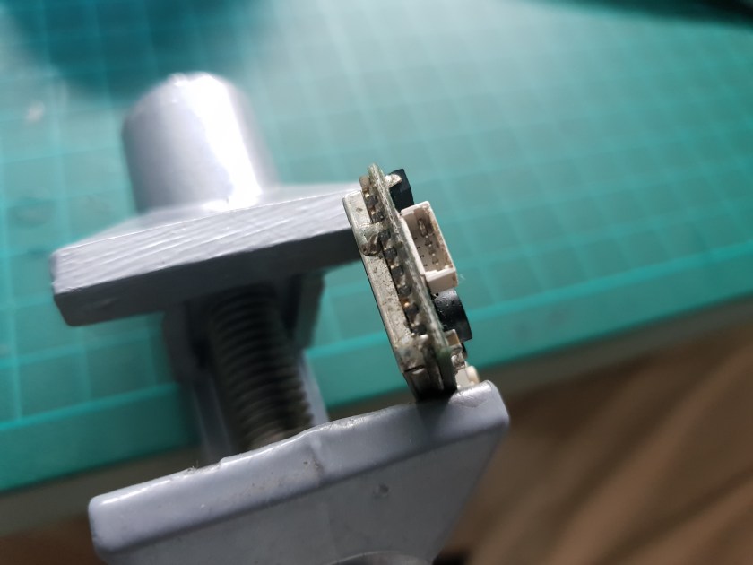
To test if the pin is straight and makes contact, I connected the plug and checked continuity between the solder joint on the board and the corresponding wire on the plug.

Powering Up
Now that the VTX has an antenna and a working connector, I can power the VTX up and see it anything else is wrong.
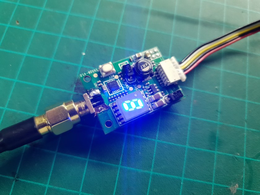
It works!
The LEDs light up, the button works and changes the settings successfully and I can see clear video in my goggles.
BTW, this is the VTX I used in the FPV video jammer I made.
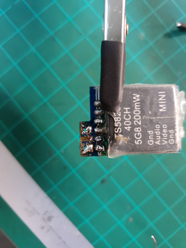
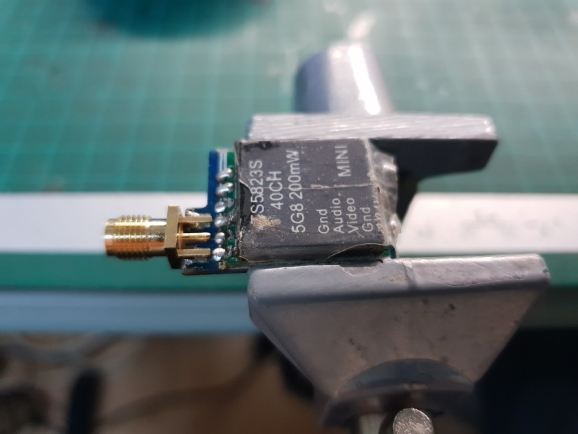
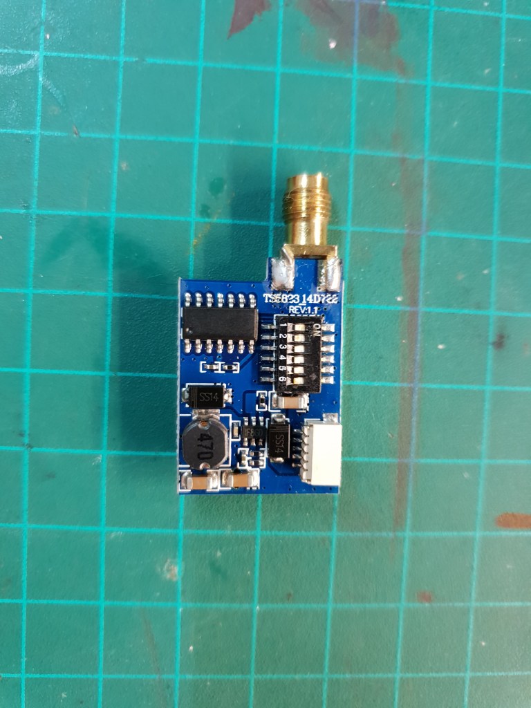
VTX #3 – TS5823S

Diagnosis
This VTX also has it’s antenna connector replaced with wires, but this time they’re still attached.
The signal cable seems to be soldered directly to the solder join between the boards, bypassing the pad that should be between the two ground pads on the bottom board. This probably means that the middle pad got ripped from the board.
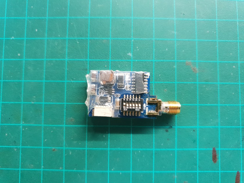
Apart from the antenna connector, everything else seems fine. No obvious signs of physical damage, the white connector looks intact and there are no burn marks or smell.

Temporary Antenna And Testing
I didn’t have any more spare SMA antenna connectors, so I hooked up a coax cable with an antenna connector in place of the wires that were there before. Much like what I did in the ATLATL VTX repair I did before.
I connected it to my FPV video jammer which doubles as a VTX tester and it seems to work. It seems that the only problem with this VTX was the broken antenna connector (and the ripped pad).


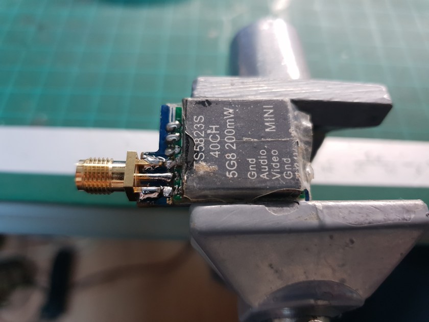
Permanent Solution
Finally, I received some antenna connectors in the mail so I can give this VTX a decent fix that will last and can survive some more crashes.
I removed the temporary cable, cleaned the solder pads with a solder wick, followed by some isopropyl alcohol and soldered on a new connector.
As can be seen in the photos, the middle pad is almost gone. There’s a tiny bit left, but the solder joint between the boards is very close so I can solder The connector pin directly to that solder joint.


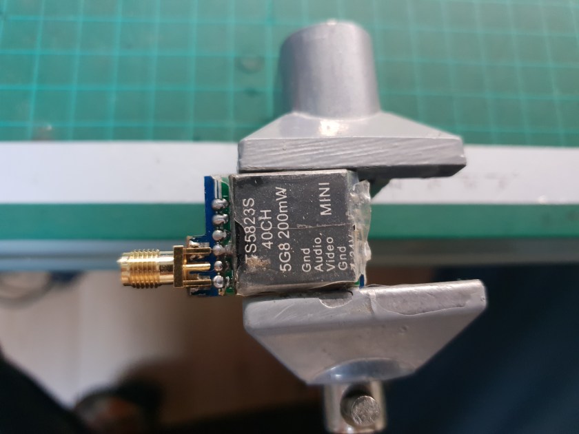
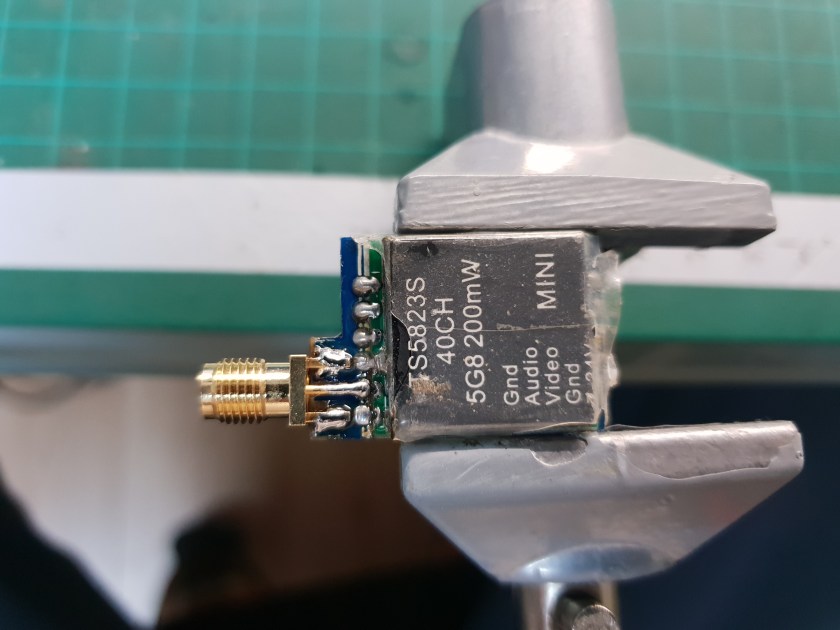
A quick re-test and it’s ready to fly again.
VTX #4 – TS5828S

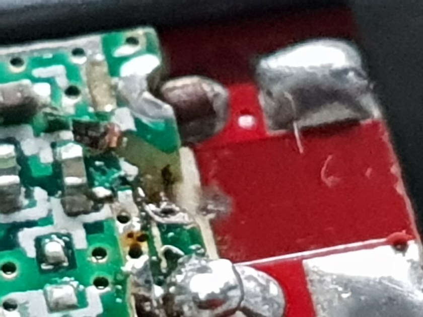
Diagnosis
This one also has it’s connector ripped off, but it has it a little worse than the previous one.
It looks like there’s no middle pad and the solder joint between the boards is completely gone.
The other side looks great, no additional damage and the connector looks good.
Following The Trace
I want to see if there’s any trace left under the shield and find the point to which it connects. If I can solder a piece of wire to that trace or point, I may be able to save this VTX.


The shield is just soldered to the ground pins on either side, removing it is pretty simple.
With it removed, I can see the trace is still connected, but it separated from the board and it’s only connected at the solder joint to a capacitor.


Is it even working?
I used a small piece of wire to connect the coax cable to what’s left of the trace and tested the VTX with the tester – we have video.


The VTX is still operational, I just need to find a way to connect the center pin of the antenna securely enough so it doesn’t disconnect in light crashes.
Fly Ready
To make it a little more resilient, I used a thicker wire, bent and connected it to the capacitor to which trace is connected rather than to the trace itself. This should be a more solid connection that will nor rip easily (at least not as easily as the tiny trace).


Another test and it’s ready for takeoff.
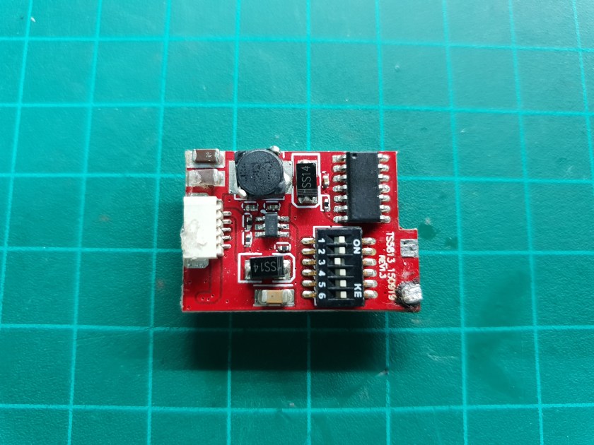
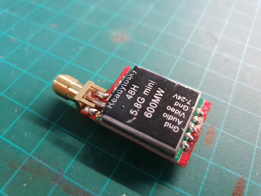
VTX #5 – Readytosky
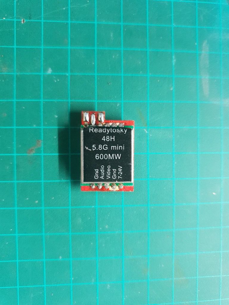
Diagnosis
Another missing antenna connector, but at least we have a full trace.
The connector on the other side is also missing, but the rest looks fine.

Testing
I connected the temporary antenna, but I need to find a way to connect power and signal.
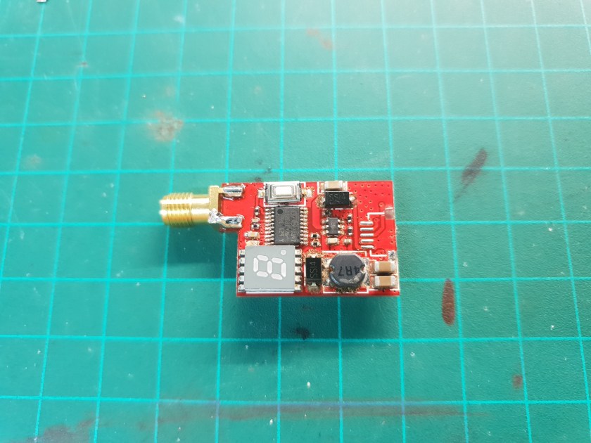
The solder pads of the connector are too fine and too close to each other to solder comfortably without risking a short. I’ll have to follow the traces from the connector pads to solder joints on the board and solder wires directly to the components on the board.
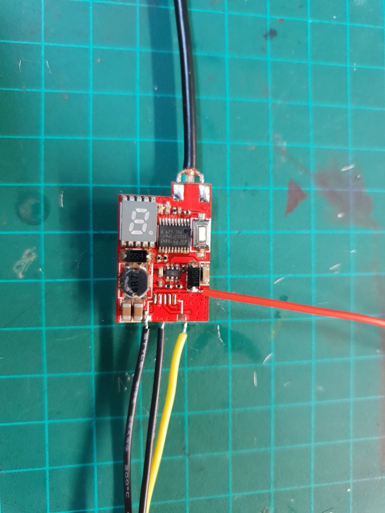


I connected power to the board and it seems to work. the LEDs light up, the button changes channels and I can see video.
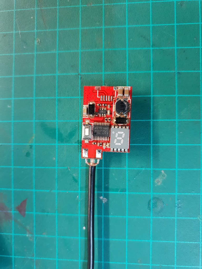
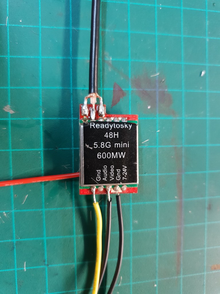
Doing What I Can
I soldered on a new antenna connector, but I don’t have any connectors for the other side.
At this point, I don’t really need that many VTX’s, so I’ll leave it connector-less for now and if I ever need it and don’t have any others, I’ll solder wires like in the testing or salvage a connector from something else.

VTX #6 – TS5823 (1)
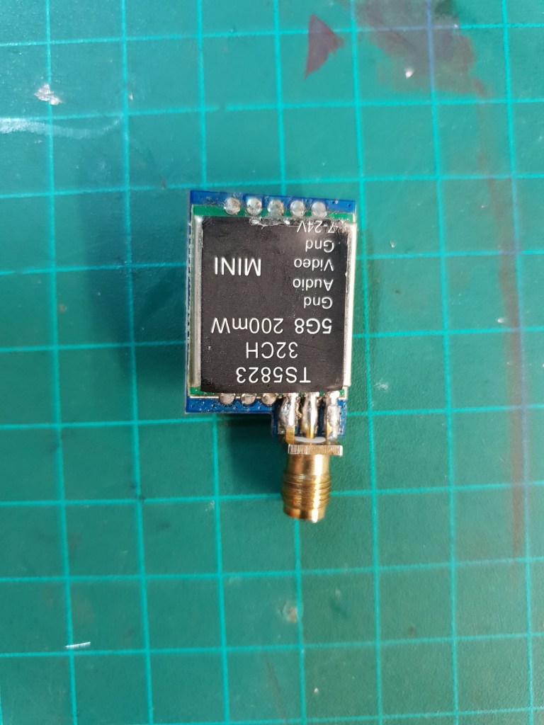
Diagnosis
This VTX looks a little beat up. The RF shield is a little crushed, but I don’t think it should be a problem.
The antenna connector seems to have been resoldered or replaced.
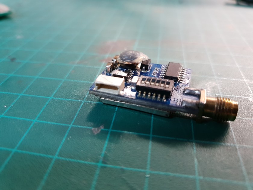
On the other side there’s some hot glue on the inductor and it seems that the top part of it is broken and almost falling off, I guess that’s why there’s hot glue there, but it isn’t dong much.
It also looks like some components were resoldered. Some capacitors are a bit crooked and the solder joints don’t look like factory ones. If the components are fine and the solder joint are intact, I think it will be fine, but we’ll verify that soon.


Testing
The white connector looks in very good condition, so testing should be easy.
I connected the VTX to the tester and it seems to work fine. LEDs, button, video – all OK.
Leaving it
The only concerning thing in this VTX is the inductor that can lose it’s top part pretty easily.
If it does lose it, I don’t think it’ll cause the VTX to stop working. It seems that the windings are fine and it’s just the top of the ferrite core that’s broken. It would probably make it less efficient and maybe be less effective in filtering noise, but it should be fine for most cases.
I don’t have any inductors that will fit in it’s place, so I’ll leave it like this and reinforce it with some electrical tape until I find a replacement inductor.
VTX #7 – TS5823 (2)

Diagnosis
This one looks great. No obvious physical damage apart from the antenna connector that seems to have been replaced or resoldered.
The other side also looks great.
Testing
Testing this VTX is pretty straight-forward. I connected it to the tester and it works great, there’s nothing wrong with this VTX.
retouching
I’ll just resolder the antenna connector to make it look a little better, but it’s not really necessary.
This was an easy one.
Conclusion

All VTX’s are in operational conditions. Some had it worse than others, but none of them had significant damage that I couldn’t fix.
One had changed it’s mode of operation, but is still working.
One still needs a new connector, but can also still be used.
One was perfectly fine from the start.
The rest are working like they should.
I think this was a pretty successful session.

hello guys, my ts5823L transmitter ran without antenna and I think the device burned.I want to repair, please help, what should I do.
LikeLike
Hi, primera1976,
If the transmitter ran at high power without an antenna and burned something inside the transmitter circuit, it would be pretty hard to fix since it’s a dense circuit with lots of tiny components.
Did any smoke come out when it happened? can you smell any burnt components?
I would first try to see if something else broke first and may have saved the transmitter itself. Are there any lights when you power it? is it getting warm? can you measure voltage at the power input of the transmitter itself?
LikeLike
hello, have you repaired maybe the damage associated with the burning of the so-called power tip (weak signal). The heat is presumed as a result of the disconnection of the tip / antenna when the transmitter strongly transmits? Is such vtx Eachine/AKK are protected by a fuse that burns in such situations?
LikeLike
Hi, I have not repaired such damage, sorry.
I’m not sure about the fuse. I haven’t seen a thermal fuse on these VTXs, perhaps they don’t have one so that it doesn’t blow mid-flight, but I don’t know for sure.
I hope you find a way to fix your issue, but it seems like a hard one to fix.
LikeLike