I bought a GTX 1080ti Founders Edition and I’m not happy with the cooling on it. The core runs at 84 degC under load and the blower on the card is very loud if I crank it up to help the cooling (by default, the fan stays at 50% regardless of the load or temps).
These temps aren’t a problem for average use, but I plan to overclock the card and it will definitely get hotter and might start thermal throttling.

I thought about buying an air-cooling solution, as I already have good airflow and can make use of it, but I found an Antec H950 pro all-in-one CPU water cooler that someone was giving away on Facebook, So I decided to turn it into a hybrid.
The guy that was giving away the AIO said it’s 4 years old, it sat for a year without use and that he doesn’t know whether it works or not. What could go wrong?!

Assessing The Damage
First, I gave it power (for a few seconds to not damage anything if something’s wrong) to check that it’s not completely dead – it’s not. It makes the right sounds, the fan is spinning and the LED in the water block seems to work. Hooray! free water cooling!
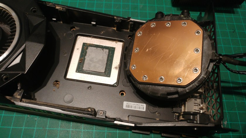
Next, I opened the block and the pump to see their condition. The pump looks very clean inside and the seals seem fine. The block, on the other hand, has some blue crust blocking the fins. It doesn’t seem to be corrosion or anything like that. The liquid that was in there had a blue tint as well, so I think it was the liquid degrading and clogging the block as it acted like a filter.
All the blue stuff came off pretty easily, I washed everything in tap water and then gave everything an alcohol bath. It seems in very good condition.


Then, I decided I will replace the existing tubes with new ones as I don’t know if this thing had any leaks during it’s life and there was some odd residue on the block’s ports that I suspect came from the blue-ish liquid inside.


Card Disassembly And Fitment
The Founders Edition has a heat sink on the core that is separated from the rest of the cooling plate. This means that if you have a water block that will fit the hole in the plate, you can keep the plate and the blower and not have to mess around with VRM cooling or void your warranty (The warranty sticker is on a screw on the other side of the card).
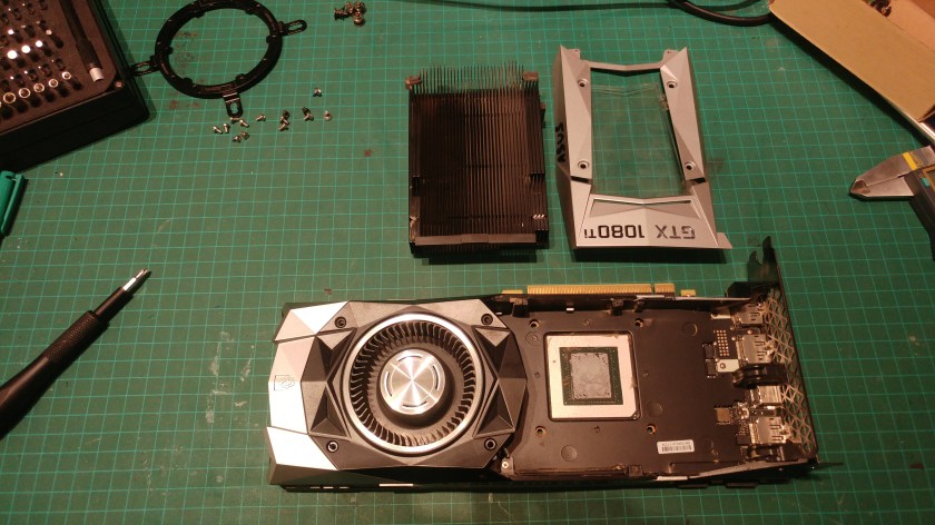
Unfortunately, my block doesn’t fit. It has a wide and flat bottom surface, where some blocks have an extruded part that gives the block some more height and clearance. Moreover, my block is meant for a CPU so the mounting holes are way off.
This means I’m either enlarging the hole in the cooling plate of the card to accommodate the wider and lower water block or pulling the plate off the card completely and replacing it with something else.
I went with the latter, as I wanted to keep the stock cooler stock so that I could put it back on and return to the original state, If I ever want to.


Making the block fit
As I mentioned, my water block is meant to be mounted on a CPU, so the holes don’t align with the holes on the graphics card.
The easy way to make it fit is to buy an adapter like the NZXT Kraken G10, but that’s cheating. We’re going to go the maker way.
Fortunately, the water block itself, without the mounting bracket, does not cover the holes on the card. This means that I can use the holes to mount a custom bracket.
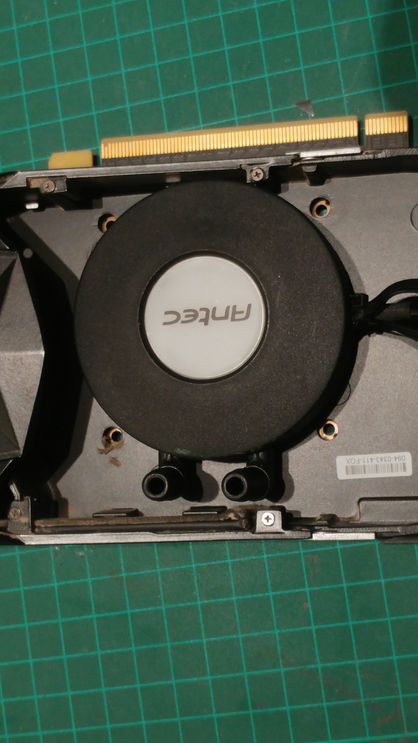
What I came up with is a 3D printed bracket that will push down on the block and keep it in place while allowing the illuminated center to show.


The file for printing the bracket can be found on Thingiverse.
Cooling A Graphics Card
It’s pretty obvious that the core needs the most cooling on the card, but there are more parts that need to be cooled to keep the card happy and to allow me to overclock.
here is a photo of the card and the parts that need cooling highlighted with red rectangles:


An easy way to tell which parts need cooling without using the internet is to see which parts have thermal pads on them conducting to the cooling plate.
In order to cool the memory and VRM, I have two types of heat sinks that I will cut to size. One with short fins for the memory that doesn’t need a lot of cooling and one with long fins for the toasty VRMs.
Since the different types of components have different heights, I can’t just cut a piece of heat sink that will cover everything (or I’ll have to route channels in it’s bottom for clearance, and that’s not easy). Instead, I cut strips of heat sinks to fit the different components separately.
I also made sure to align the fins with the airflow of my case, since I’m not planning on putting a dedicated fan on there.


The original thermal pads were full of dust and were falling apart so I replaced all of them with fresh thermal adhesive tape, as they will not be screwed to the PCB. later we’ll see that it wasn’t enough.
Rebuilding The Loop And Initial Testing
Refilling the loop was a little bit tricky because there is no reservoir to fill and allow air to escape.
What I did was make a temporary reservoir from an open jar and put it between the pump’s inlet and the radiator, meaning there’s a hose coming from the pump and a hose coming from the radiator, sitting in the jar that’s full of liquid. The tricky part is converting this into a short connection between the pump and radiator once the loop is full, without spilling the water in the loop.
All the other hoses were pretty straight forward to install. The connectors on all the components are simple ones that just press inside the hose (with zip-ties for security).
I filled the loop with straight distilled water. No additives or colors yet.
To fill the loop I had to suck air out of the radiator outlet until water went in and out of the pump, then connect power and quickly put the hose back into the jar. This is because this type of pump is not self-priming, meaning it can’t suck air to pull water from the jar, it has to have water inside it before it’s powered up.
After the loop was full and all the air was removed (by rotating and flipping the block and radiator to allow the air at the high spots above the hose holes to escape), I let it run for a few minutes to make sure that there are no major leaks, no residue from the old liquid and that the loop itself is working.
The test was a success.
I pinched the radiator hose where I wanted to cut it and shut the pump down. Then I cut the hose and in one motion pulled the hose from the pump inlet and pushed the one I had pinched on to the pump instead of it.
I ended up with a little air bubble, but it quickly found its place in the top part of the radiator, never to be pulled into the loop again.
Another short test and I installed the block on the card.

Mounting In The Case And Real World Testing
There are a few ways I could mount the radiator. I initially wanted the radiator on an exhaust fan, blowing the hot air outside, but I only have one fan that fit the bill, and it is too close to the CPU cooler to mount the radiator inside the case. I could mount the radiator on the outside of the case with the hoses running through the dedicated holes in the case, but that would mean that I have to take the loop apart in order to take it out and put it in. Not ideal.
Eventually, I settled for a front intake fan. This way, the radiator will be hidden and I wouldn’t have to take everything apart whenever I want to swap components or maintain something. The only theoretical problem is that the air that is supposed to cool the CPU and MoBo is hotter.
I knew mounting everything in the case wouldn’t be trivial. I have an Antec 900 (gen 1) which has plenty of room in the front, but the drive cages and the front covers that are attached to them only go in from the outside. This means that I have to get the card itself in from the front of the case.
Fortunately, The front covers can be mounted to the case without the drive cages (normally, the front covers are attached to the fan mounts which are mounted to the drive cages, which mount to the case itself).
I mounted the fan and fan mount to the radiator by drilling through the screw holes in the fan mount and mounting the fan straight to the radiator with the fan mount sandwiched in between. The front covers went on top.

2 Minutes after installing the card and one of the heat sinks fell. The adhesive isn’t strong enough to keep the biggest heat sink in place and touching anything on the card risks more heat sinks falling. I’m not powering the card like this, I need something to secure the heat sinks in place.
As a temporary solution, because I’ve been gaming with my “old” GTX 1070 and I’m missing the performance of the GTX 1080ti, I took a piece of 100x100x0.5mm aluminium and some foam, drilled holes according to the ones on the card and put it on top of the heat sinks.
This will restrict airflow somewhat, but it should be enough.


It’s time to pray. Pray that I didn’t kill the card during the weeks it sat disassembled waiting for items to arrive in the mail and all the times it was taken in and out of the anti-static bag for measurement and fitment testing.
And… It works! The card is fine, the loop is working and we are getting good temps for now so we know the block is mounted correctly. Time for some real tests.
I started Aida64 on a GPU only stress test. After about 30 mins I could see the core did not go above 59 degC, being most of the time around 55 with some peaks. That’s a big improvement. I let it run a while longer and the results didn’t change.
In long gaming sessions I saw the same effect, peaking at 60 degC.
That’s plenty of headroom for overclocking.
Ideas For Improvement And Upgrades
Aesthetically, there’s a lot that can be done. I can make a better looking top plate to hold the heat sinks in place, preferably something with holes to allow air to pass from different directions.
Also, the controller inside the block is acting pretty strange, it makes the RPM of the fan fluctuate regardless of the load or temps, this wouldn’t bother me if the fan didn’t make revving sounds like it’s at a car show.
I tried downloading the Antec software and connecting the block to a USB port to try and manually control it, but it didn’t help.
I’m not sure if there’s something wrong with the controller or if that’s how it’s supposed to act, but I figured I don’t really need the controller anyway. The way I installed the radiator, I want the fan to work at moderately low RPM all the time to provide airflow for the CPU cooler even when the GPU is idle. The thermistor or thermocouple (not sure what they have in there) in the block is nice, but also unnecessary and the GRB LED can be controlled in countless other ways.
Removing the controller brings a few benefits, like not having 3 ugly cables coming out of the block and going to 3 different places (power from the MoBo, USB on the MoBo, power to the fan and pump).
I might as well replace the fan to a more quiet one that will be controlled by the MoBo.
I could also 3D print some cool structure in translucent filament and mount it on top of the block so it’s illuminated by the LED.
I may drill holes in the heat sinks and put thermocouples in there to monitor memory and VRM temps and make sure they are sufficiently cooled.

Wow amazing ! !
Looking forward to see how the oveclocking goes.
LikeLike
Yes, very cool. I wonder how safe it is! probably very.
LikeLike
I went over this site and I conceive you have a lot of wonderful info , saved to my bookmarks (:.
LikeLike