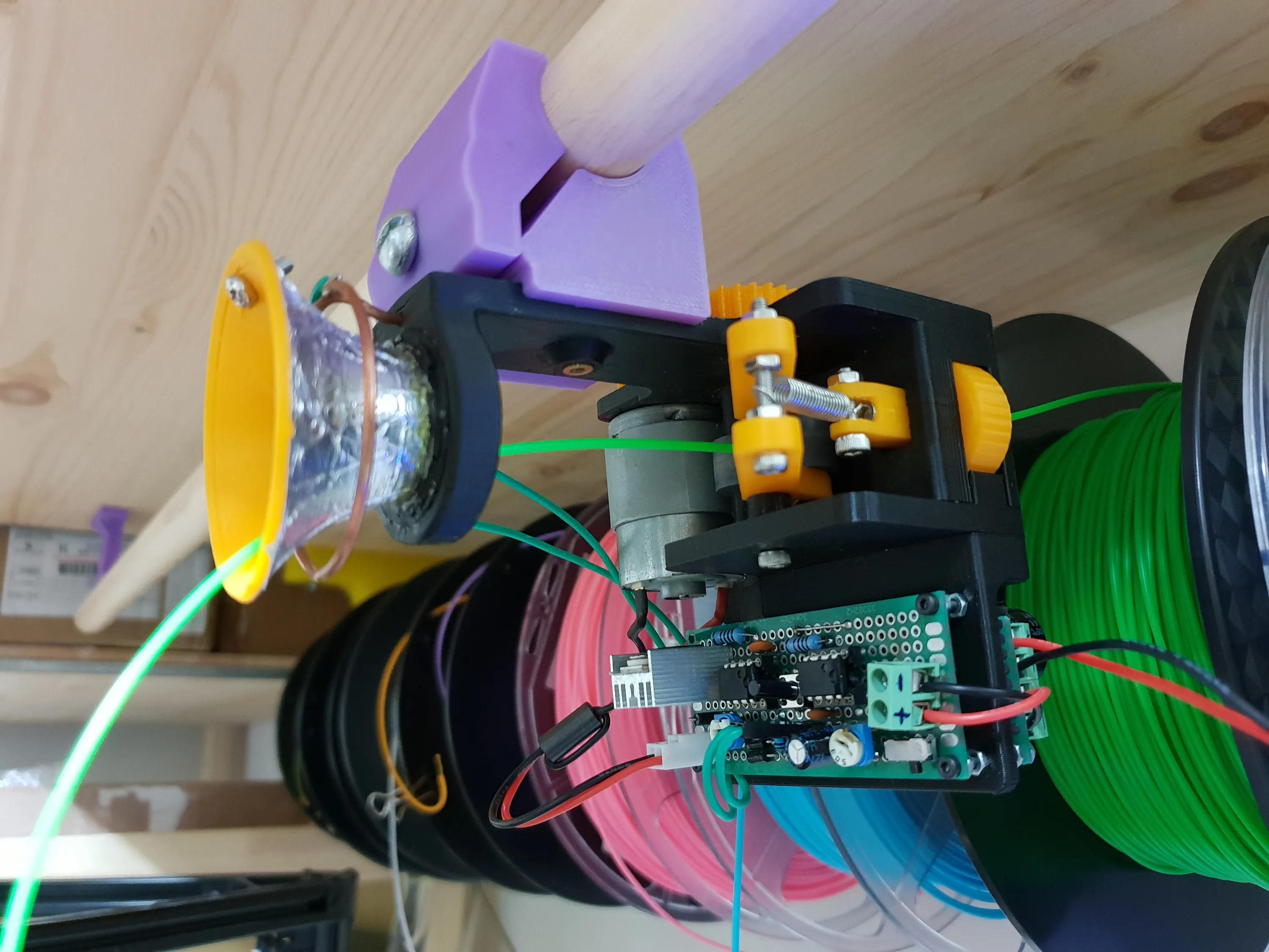
Active Strain Relief for 3D Printer filament
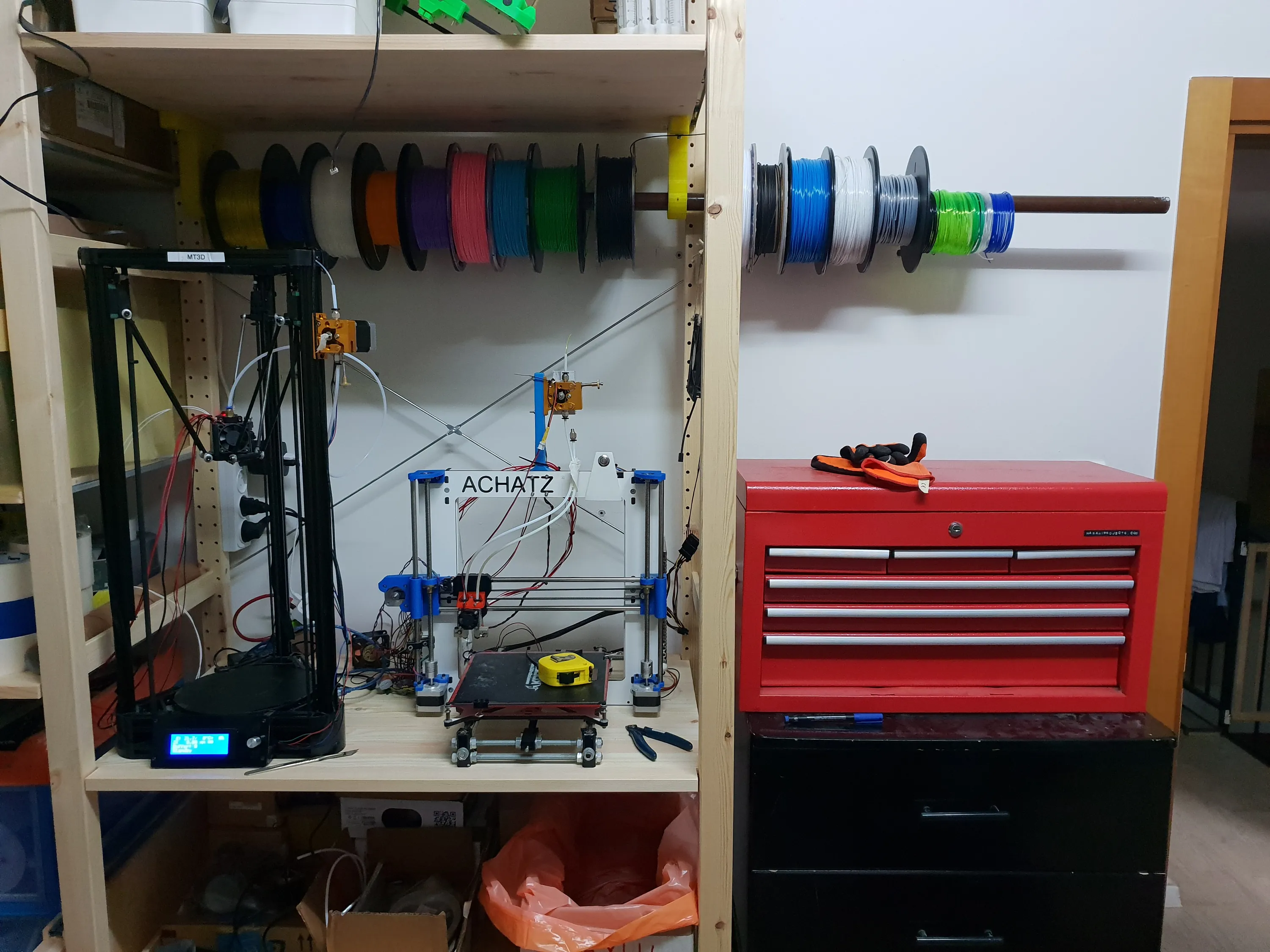
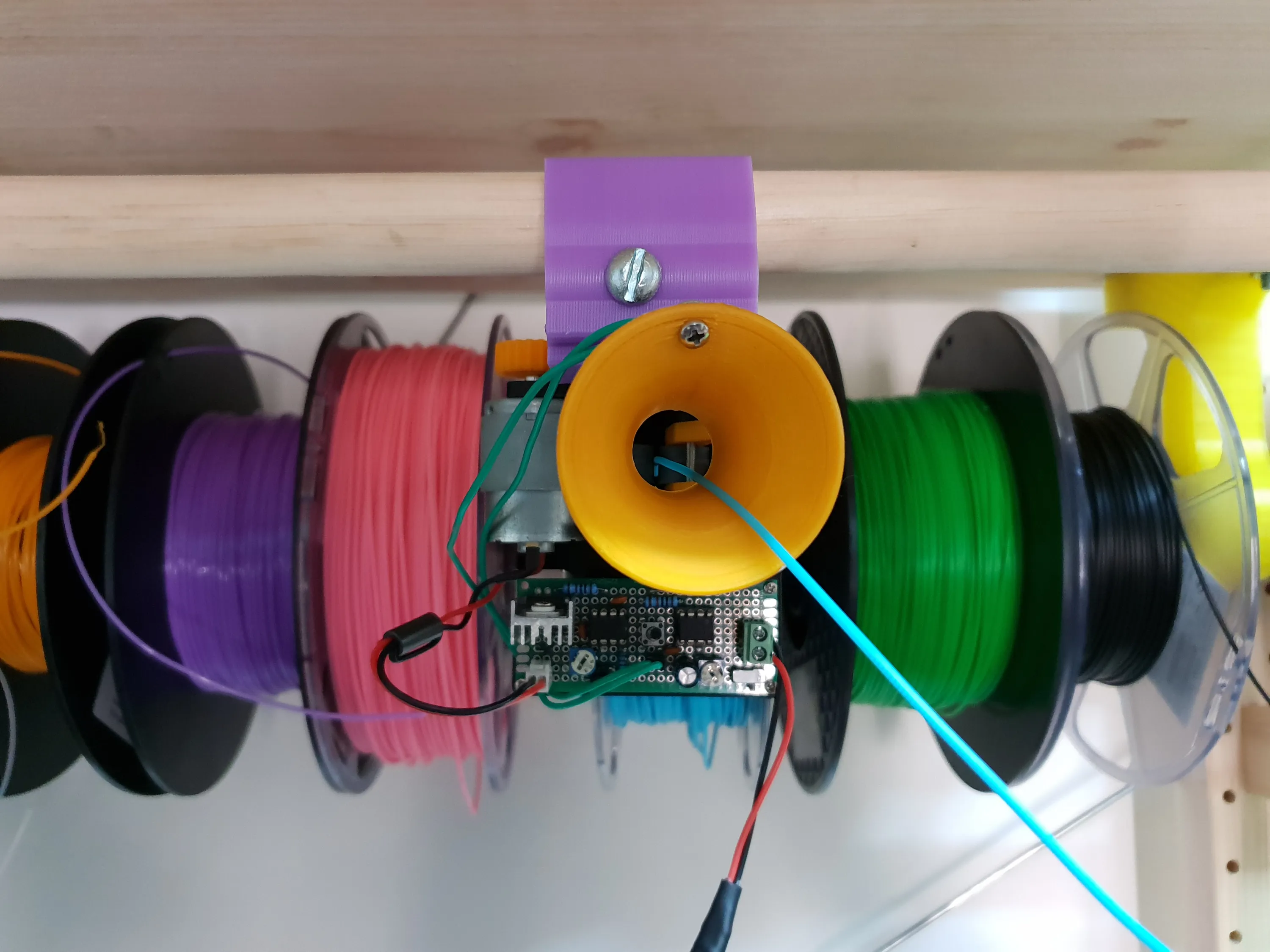
As you can see from the below picture, I hang my filaments above my printers and just pull the one I want.This is fine if the filament is close to being directly above the printer, that way the filament is pulled parallel to the spool.Sometimes I need to use the out-most filament spool, this is a problem because the filament wants to unspool and it’s harder for the extruder to pull. I don’t care that much that the filament unspools, but there’s a risk of it getting tangled in other spools and making it hard on the extruder, causing gaps in prints.
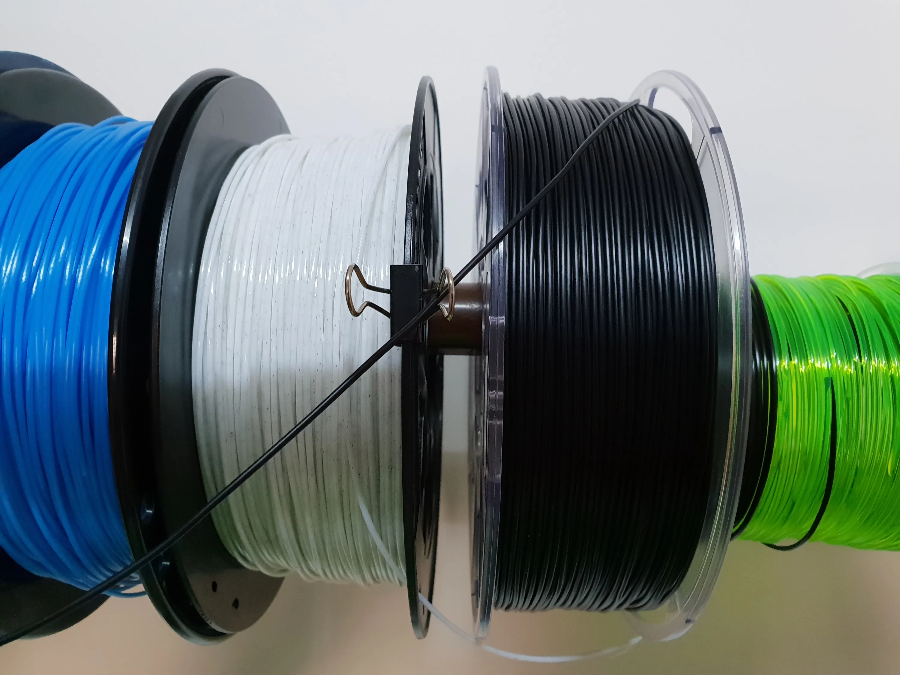
My solution for this was a small paper clip attached to the adjacent spool that functioned as a guide for the filament. This way, there’s no unspooling, but the filament still has to bend sharply and is not as easy to pull as the ones directly above the extruder.
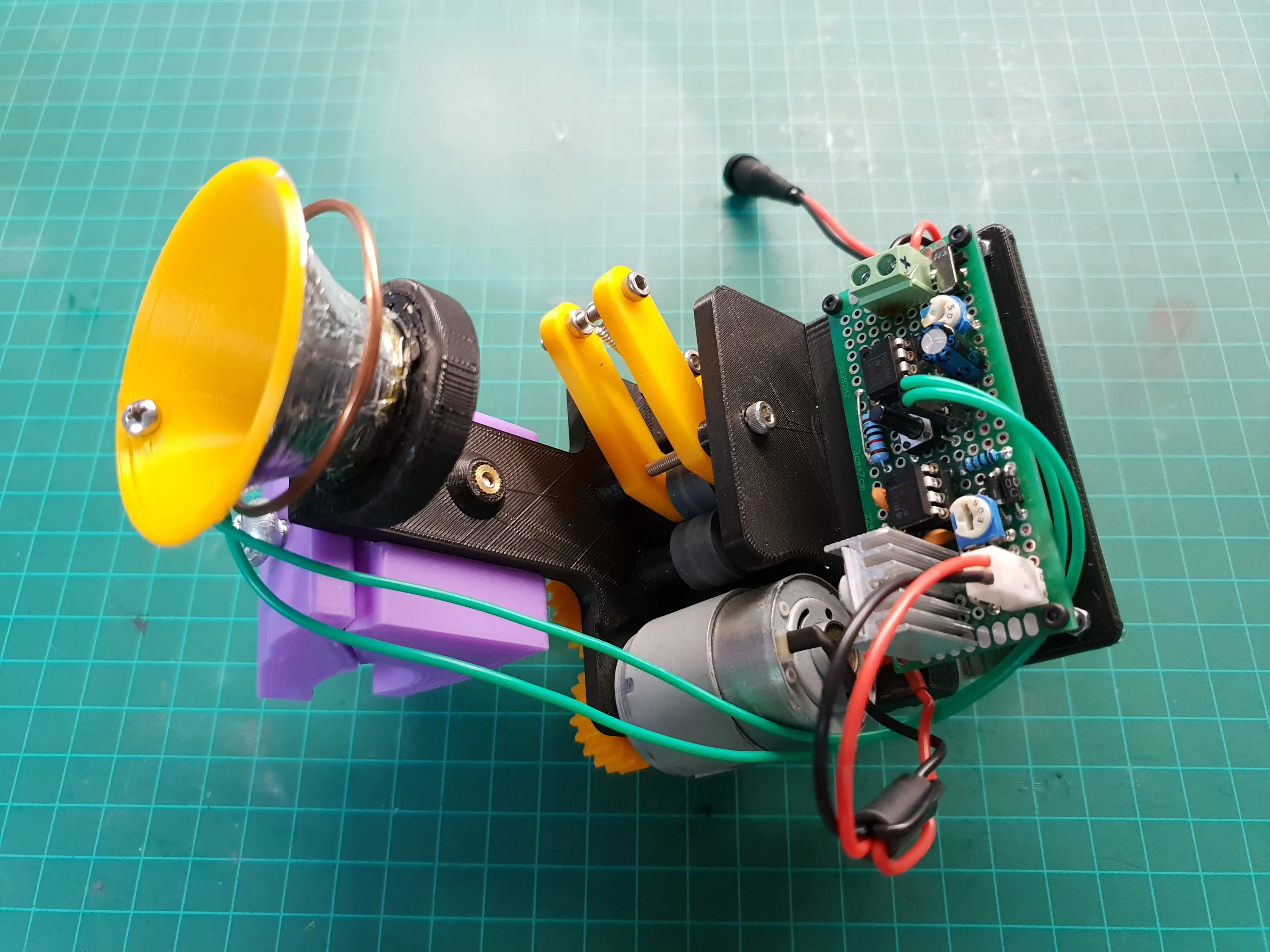
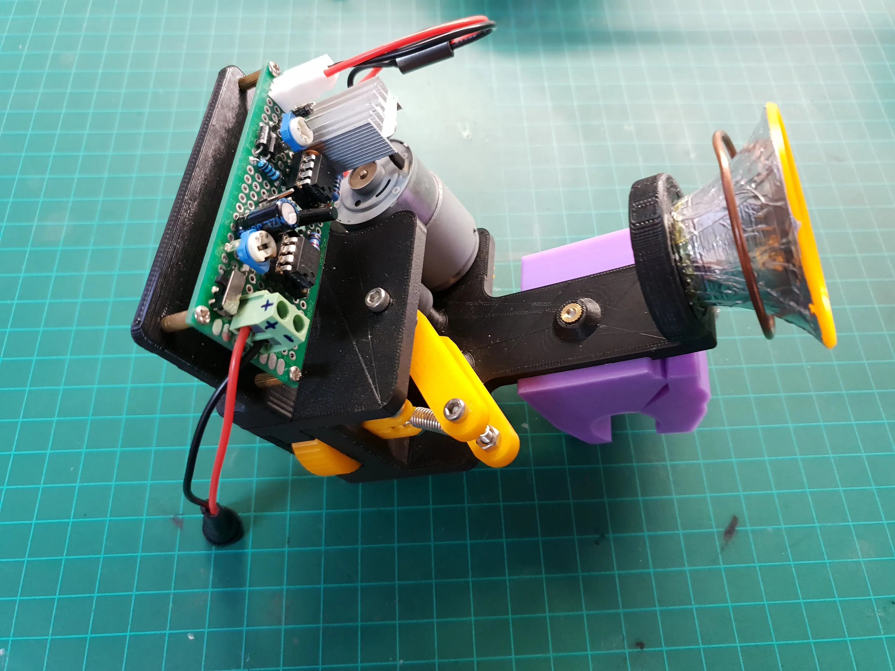
What I need is something that will pull the filament parallel to the spool and relieve the tension from the filament so that there would be no resistance before the extruder. In other words, I need a filament “buffer” before the extruder.This is what I came up with:
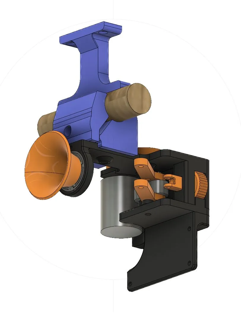
I call it “Active Strain Relief”. It’s basically a weak extruder that doesn’t dig into the filament and is triggered via the force that is applied to the filament by the printer’s extruder.
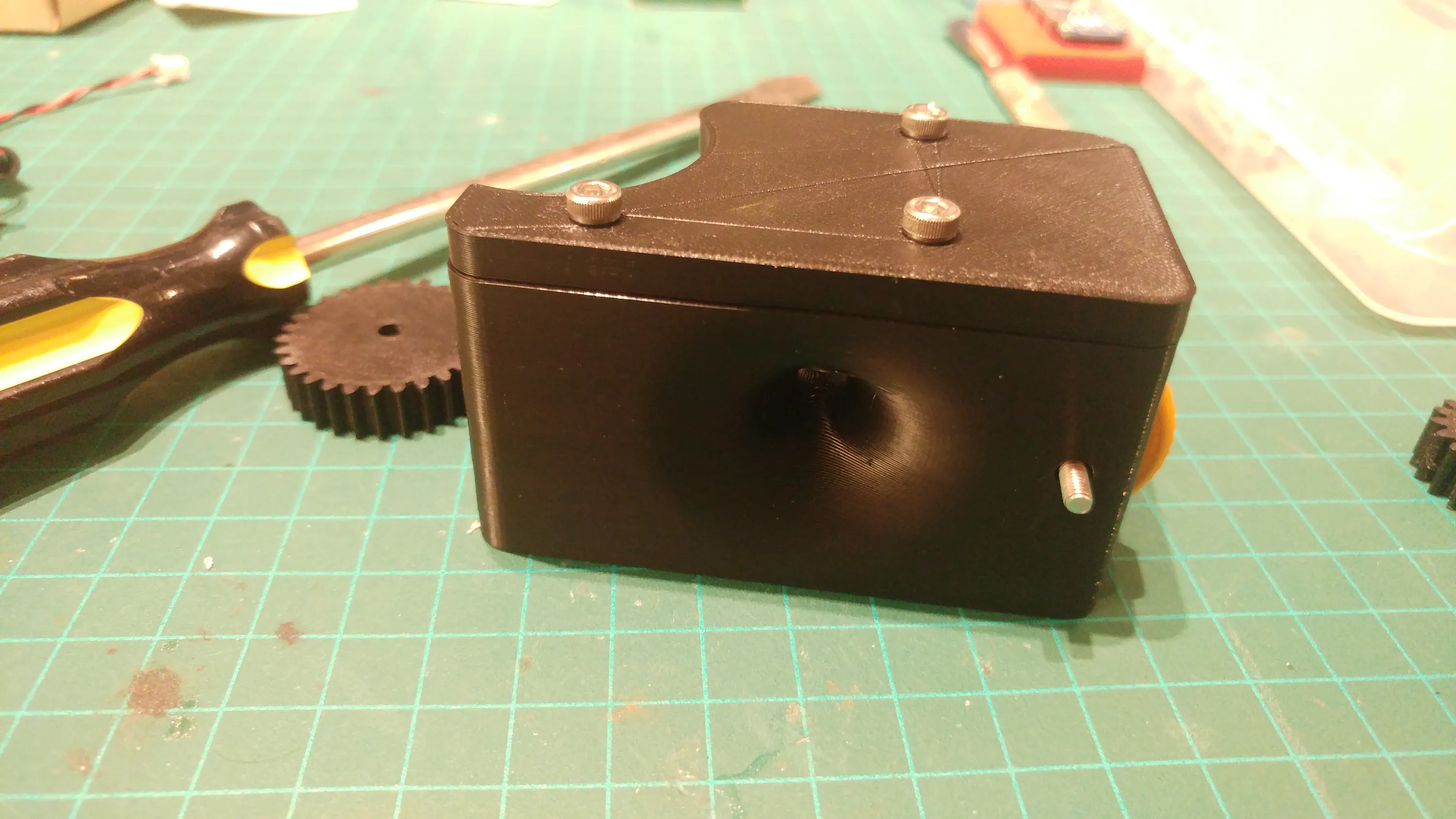
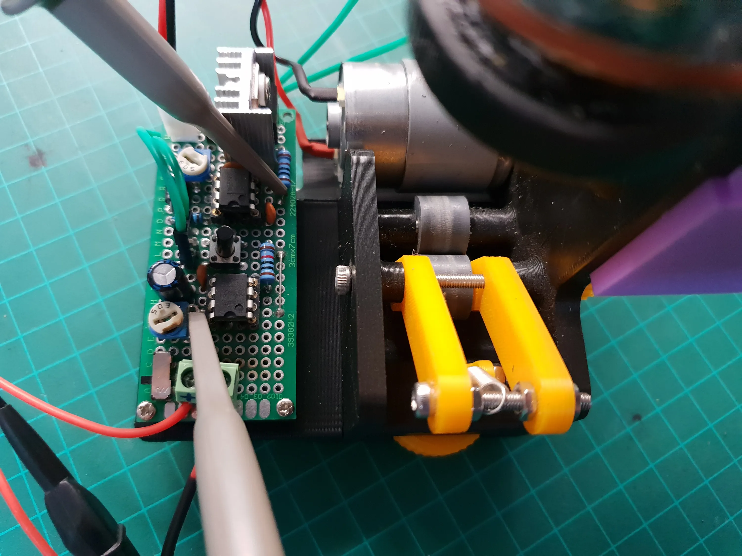
The Driving Mechanism
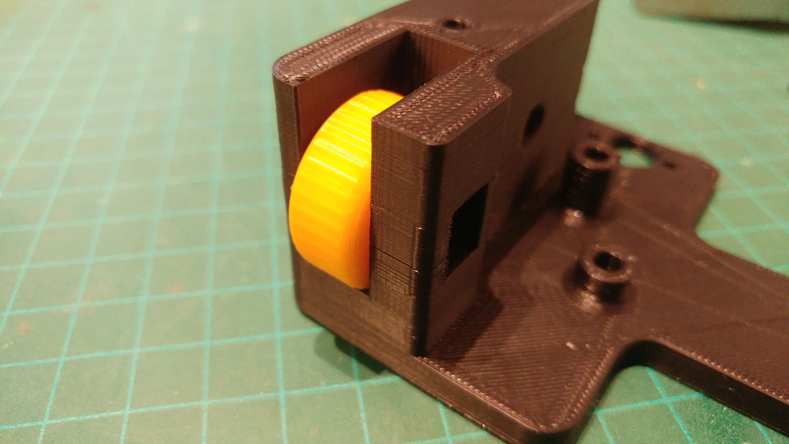
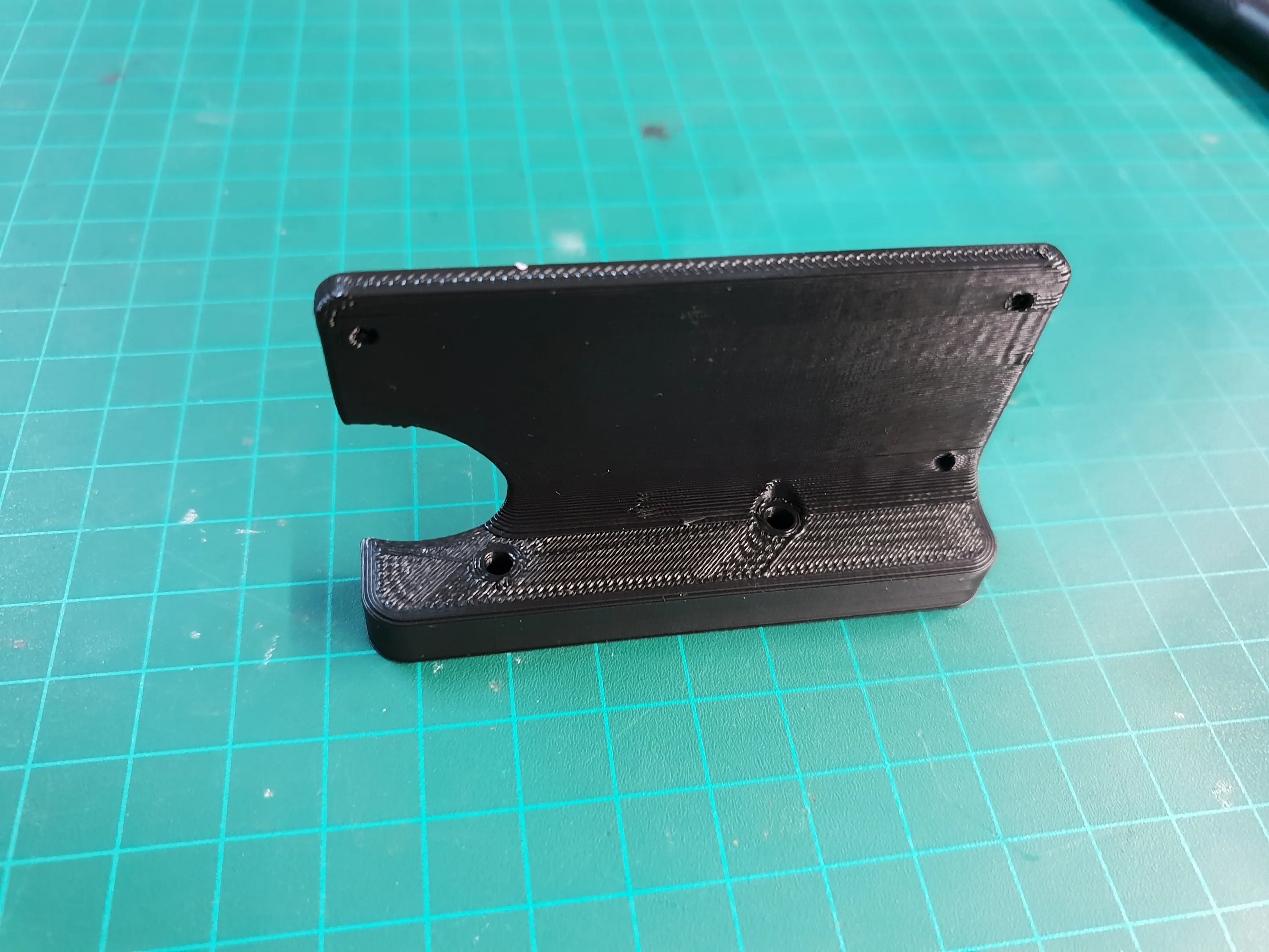
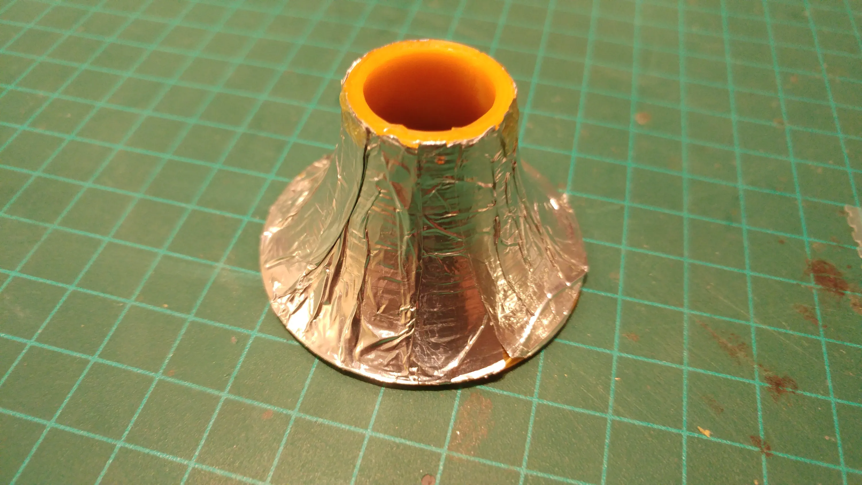
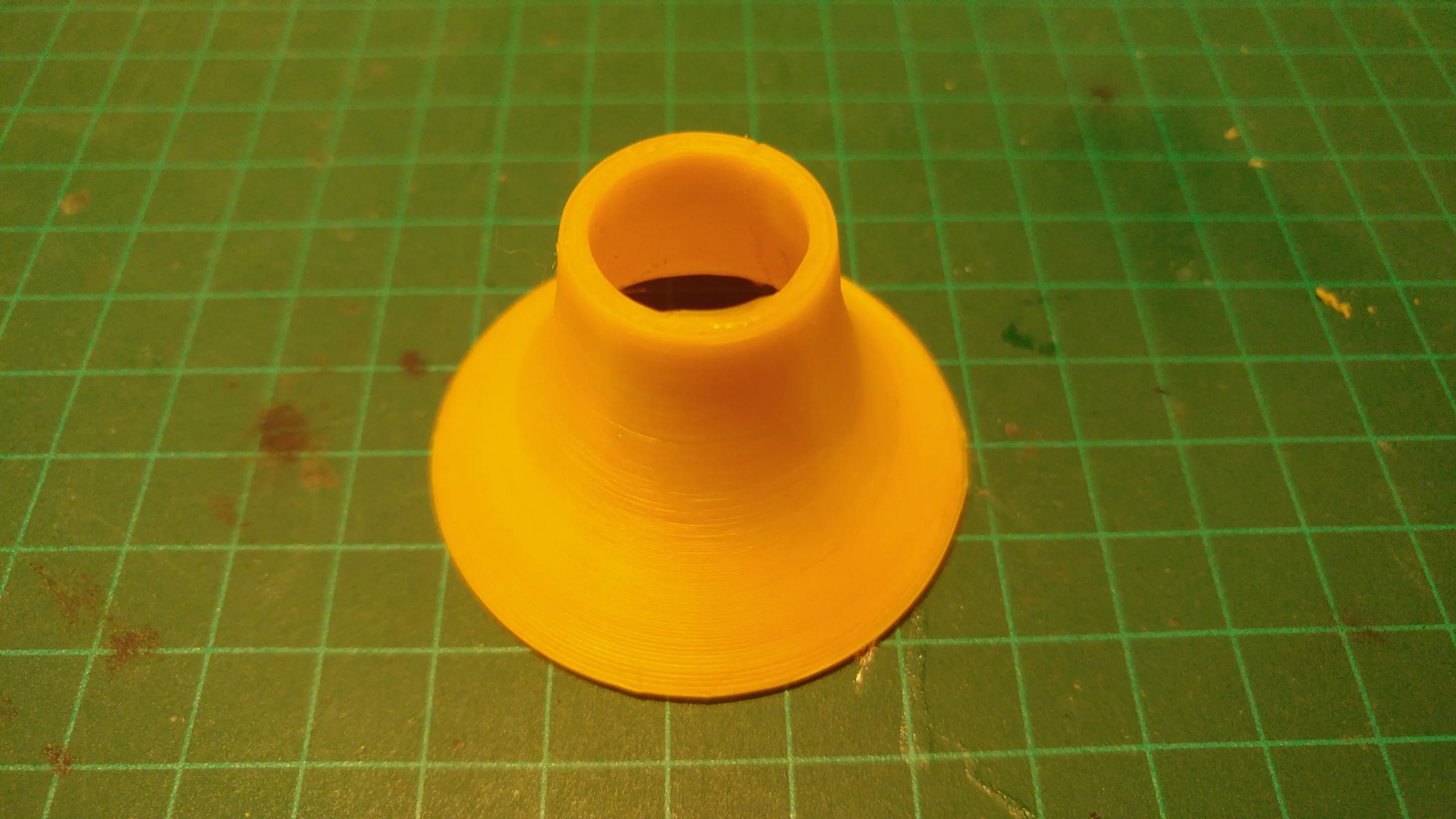
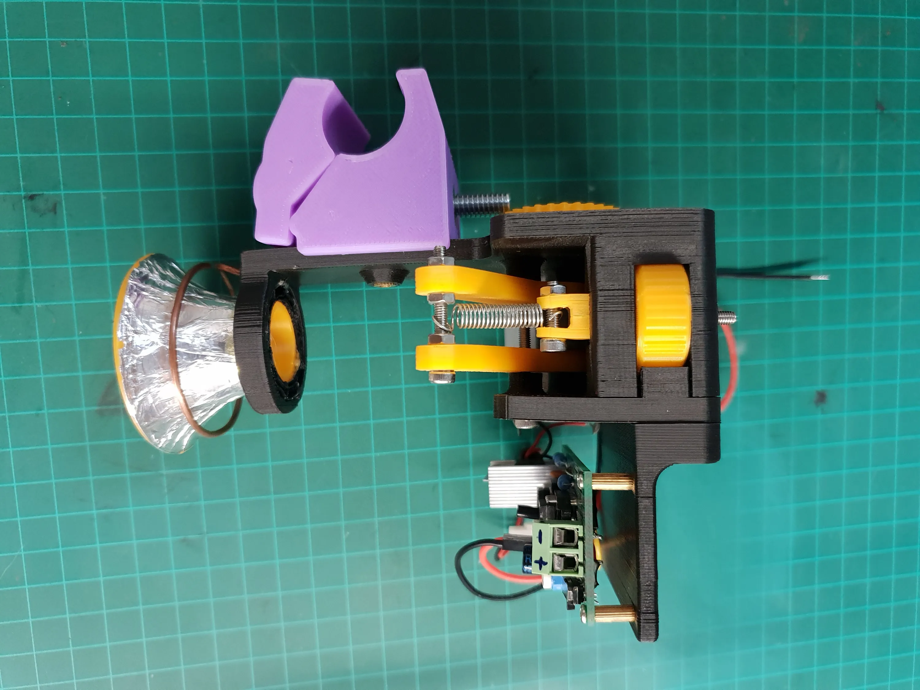
The filament enters the mechanism through a tapered hole that also acts as a 360 degrees guide to prevent the filament from grinding or binding on an edge.
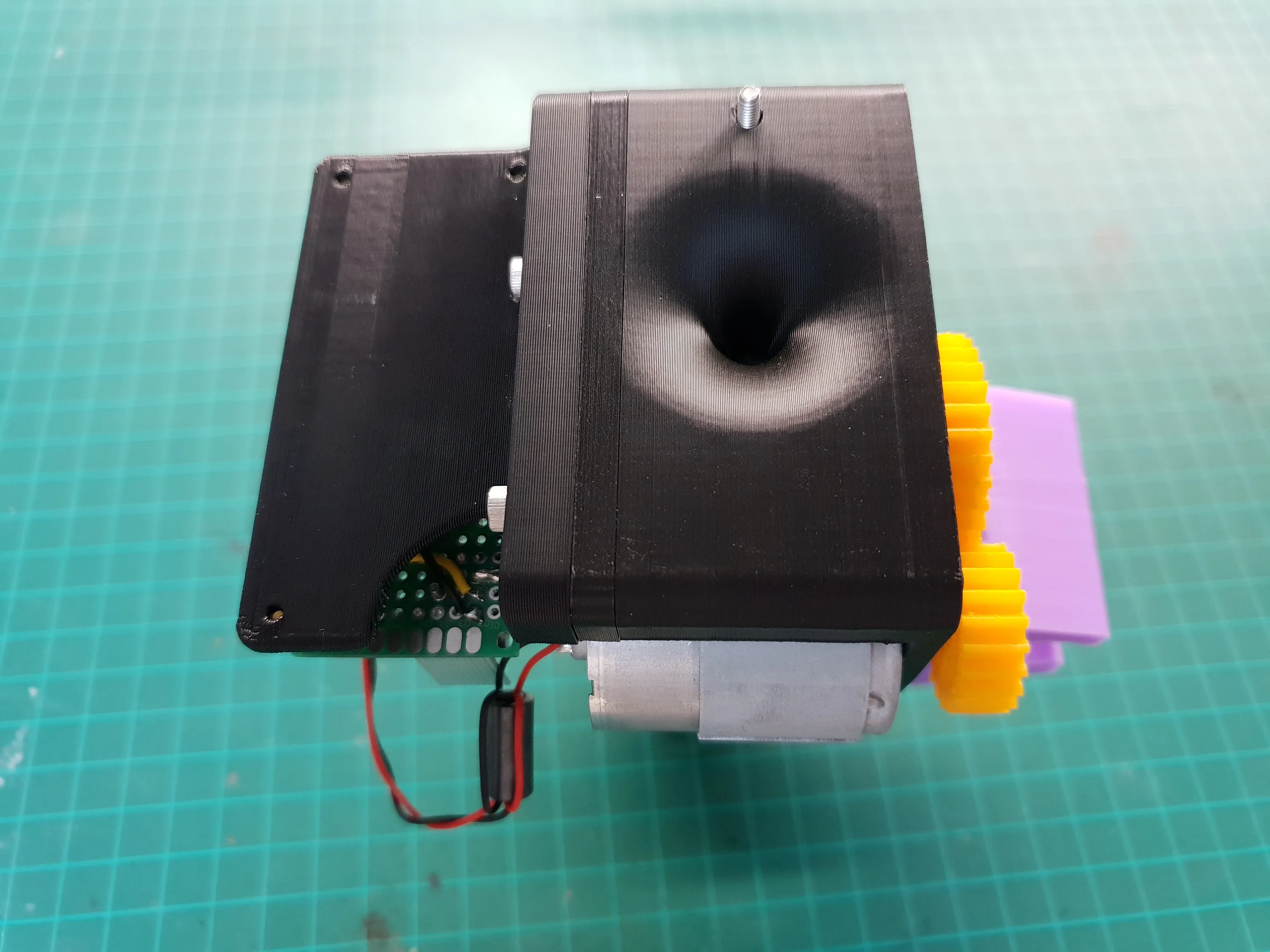
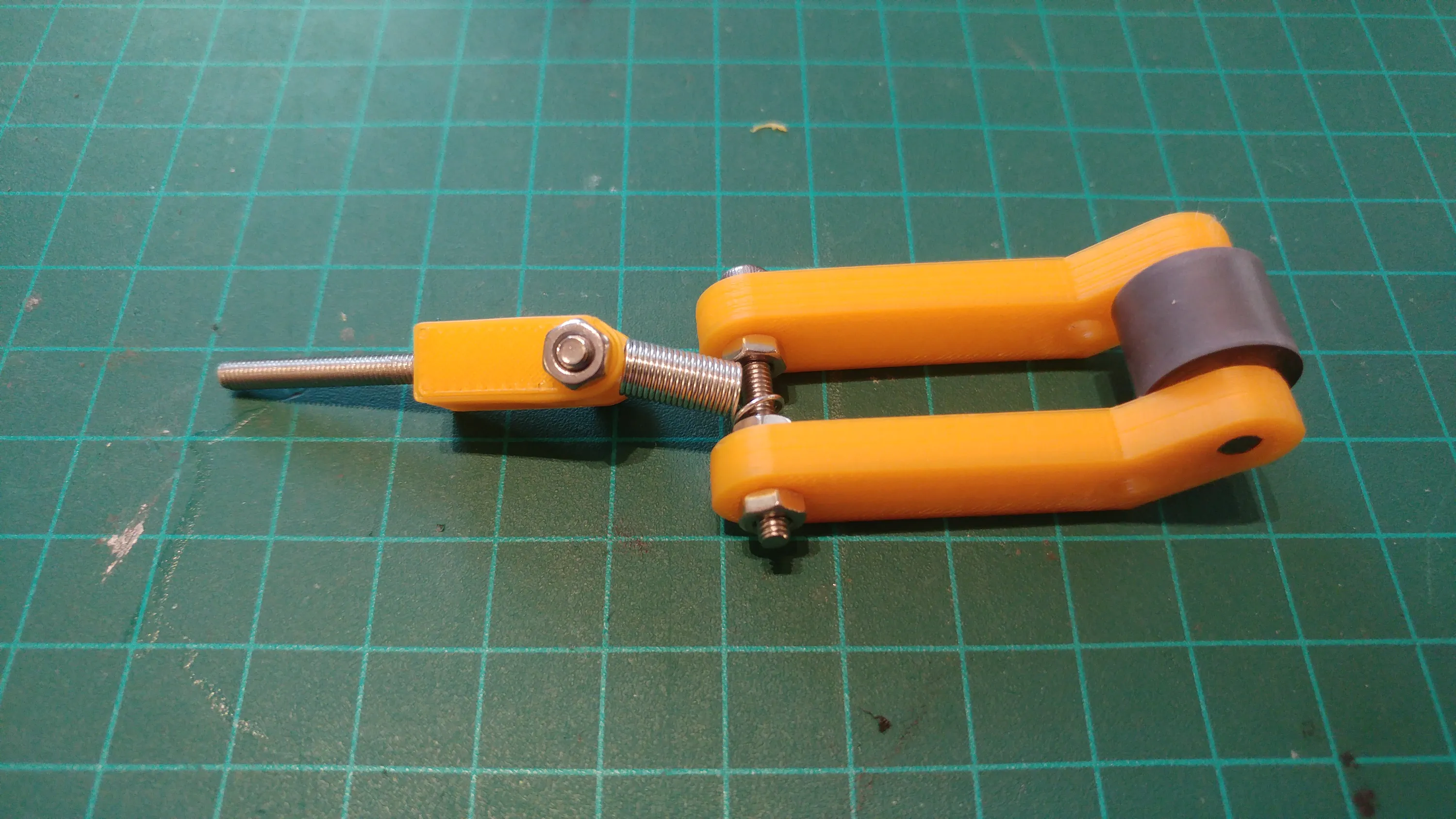
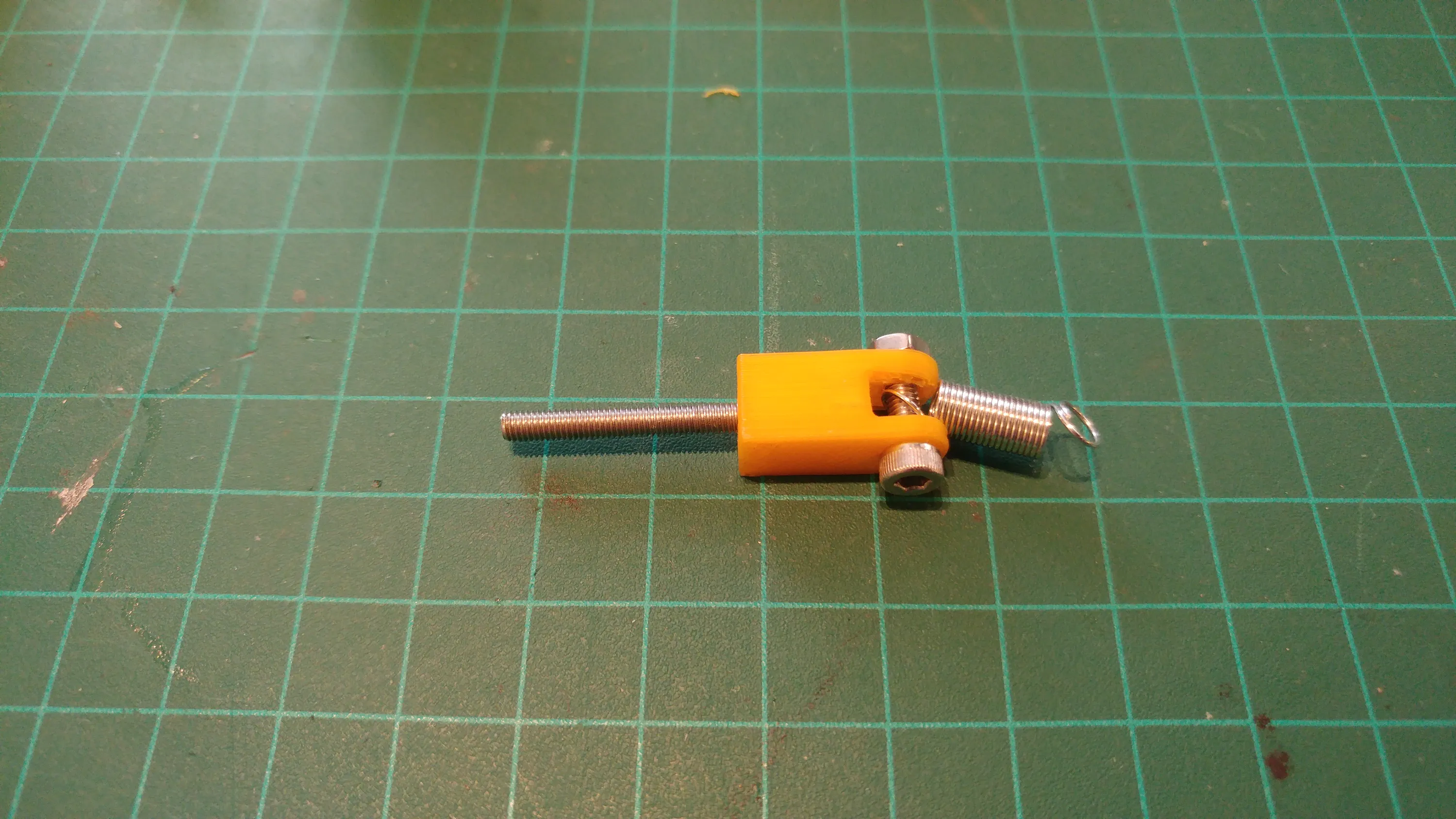
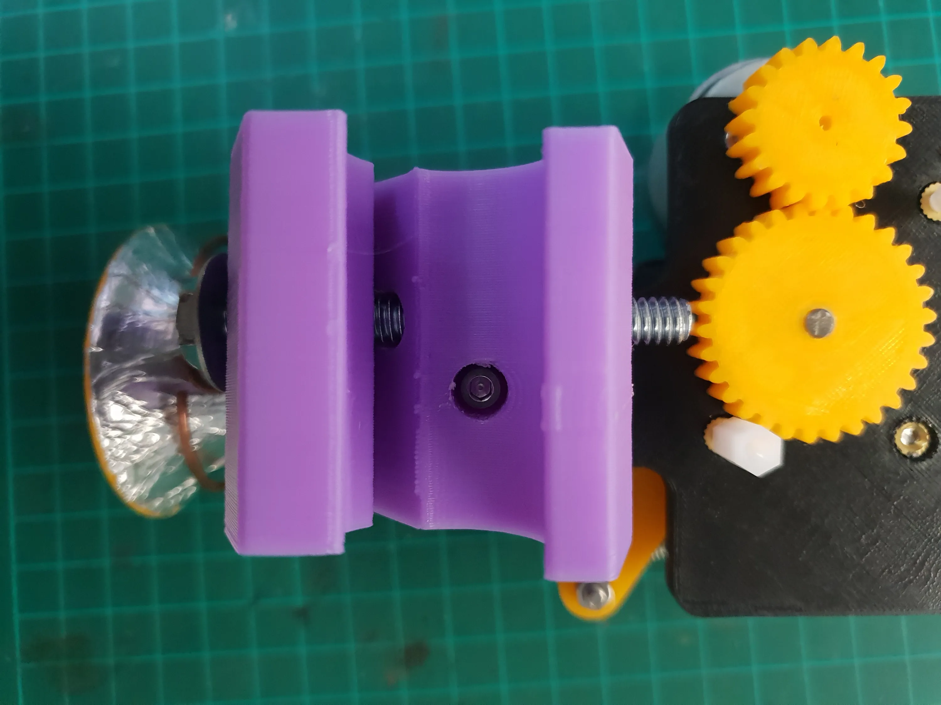
Then, the filament is pinched between two rubber cylinders that came from an inkjet printer. The force applied to the filament can be adjusted via the wheel on the side which adjusts the tension in the spring.
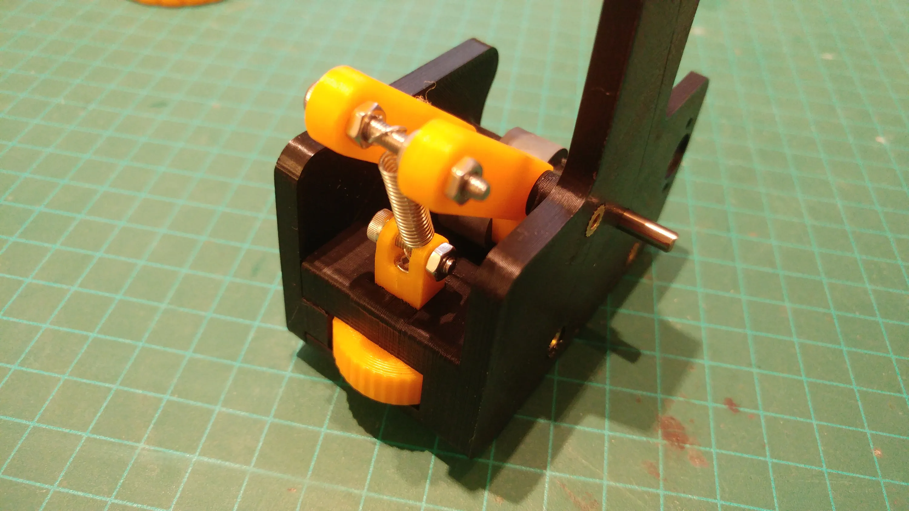
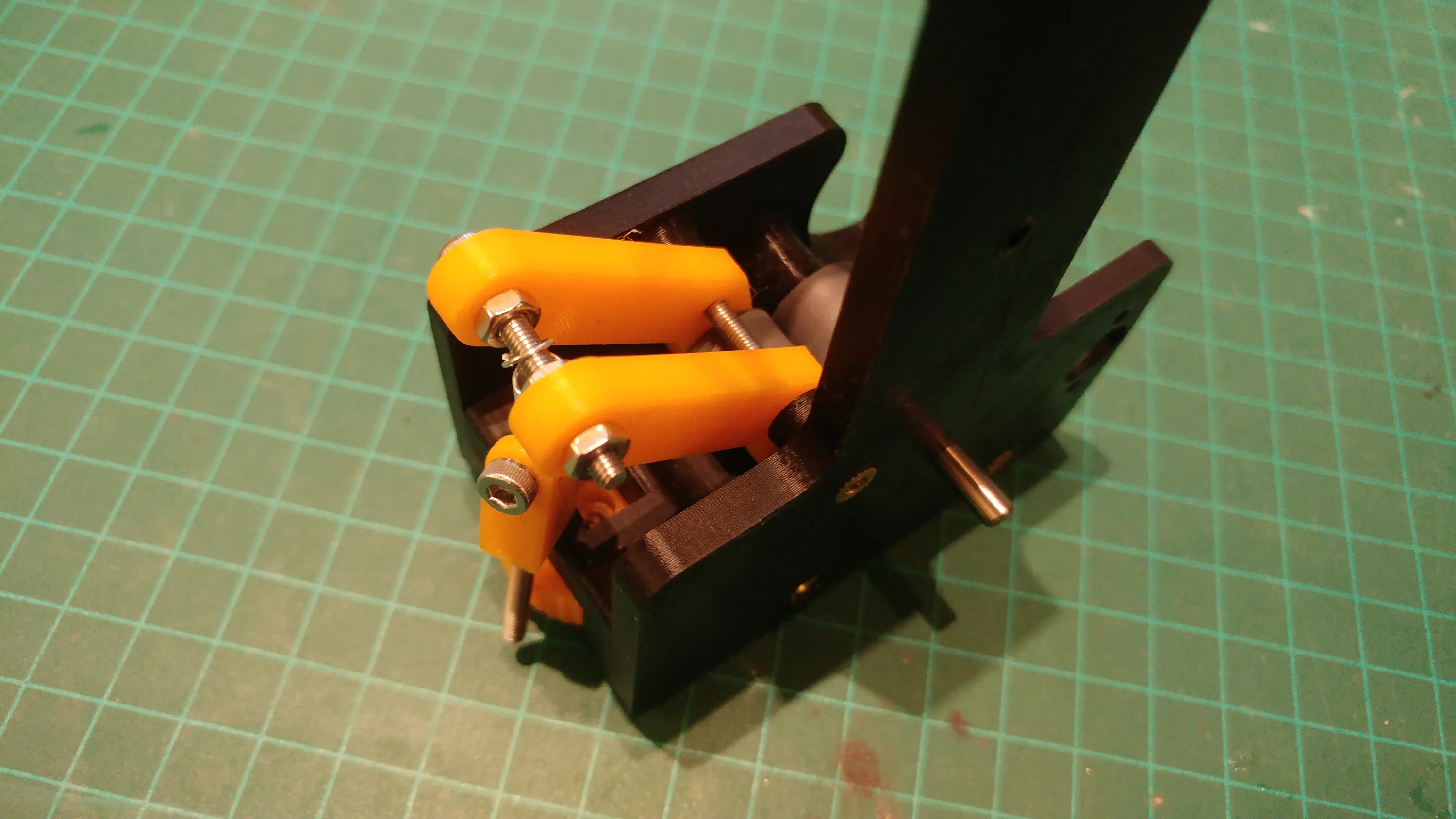
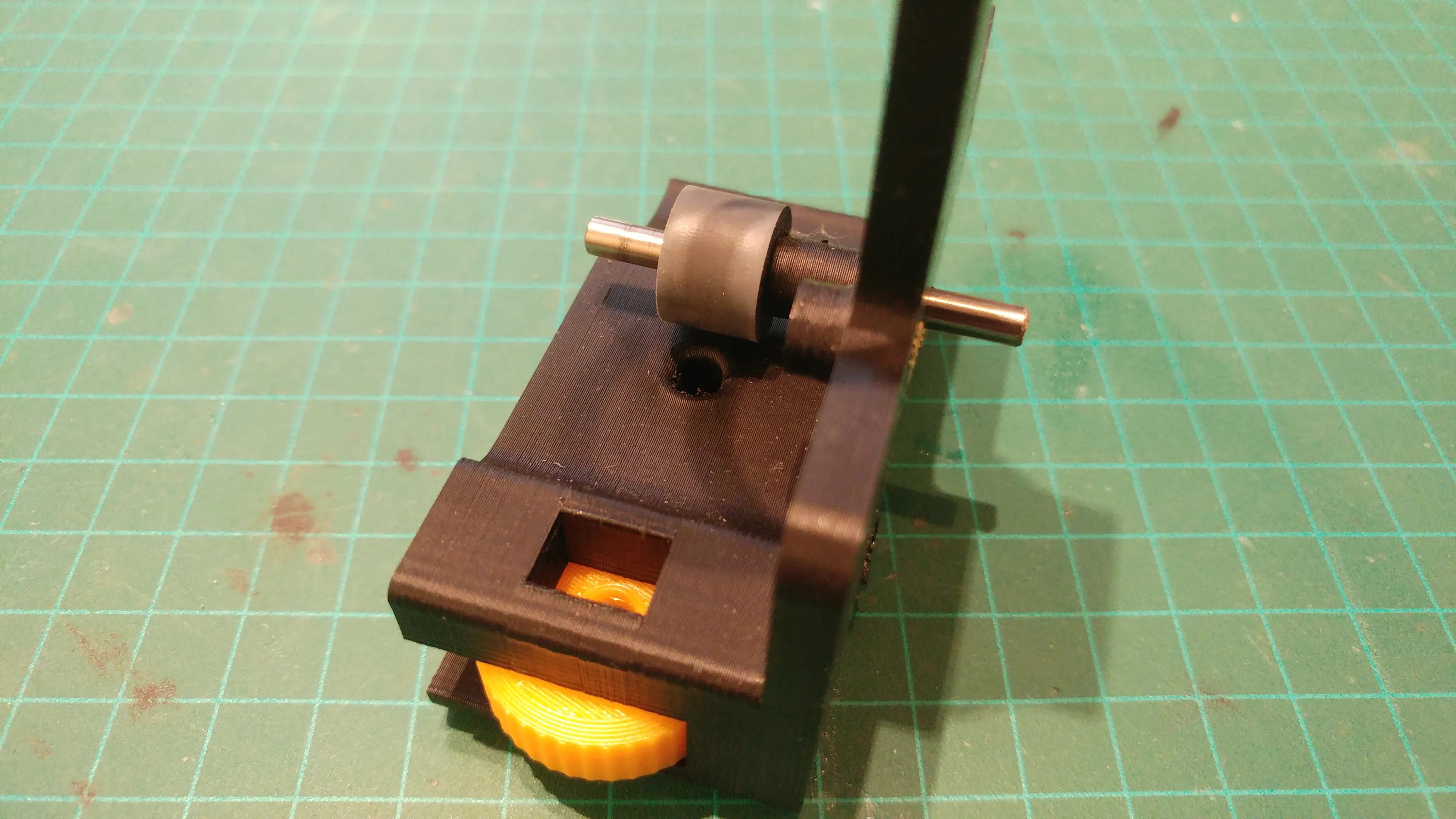
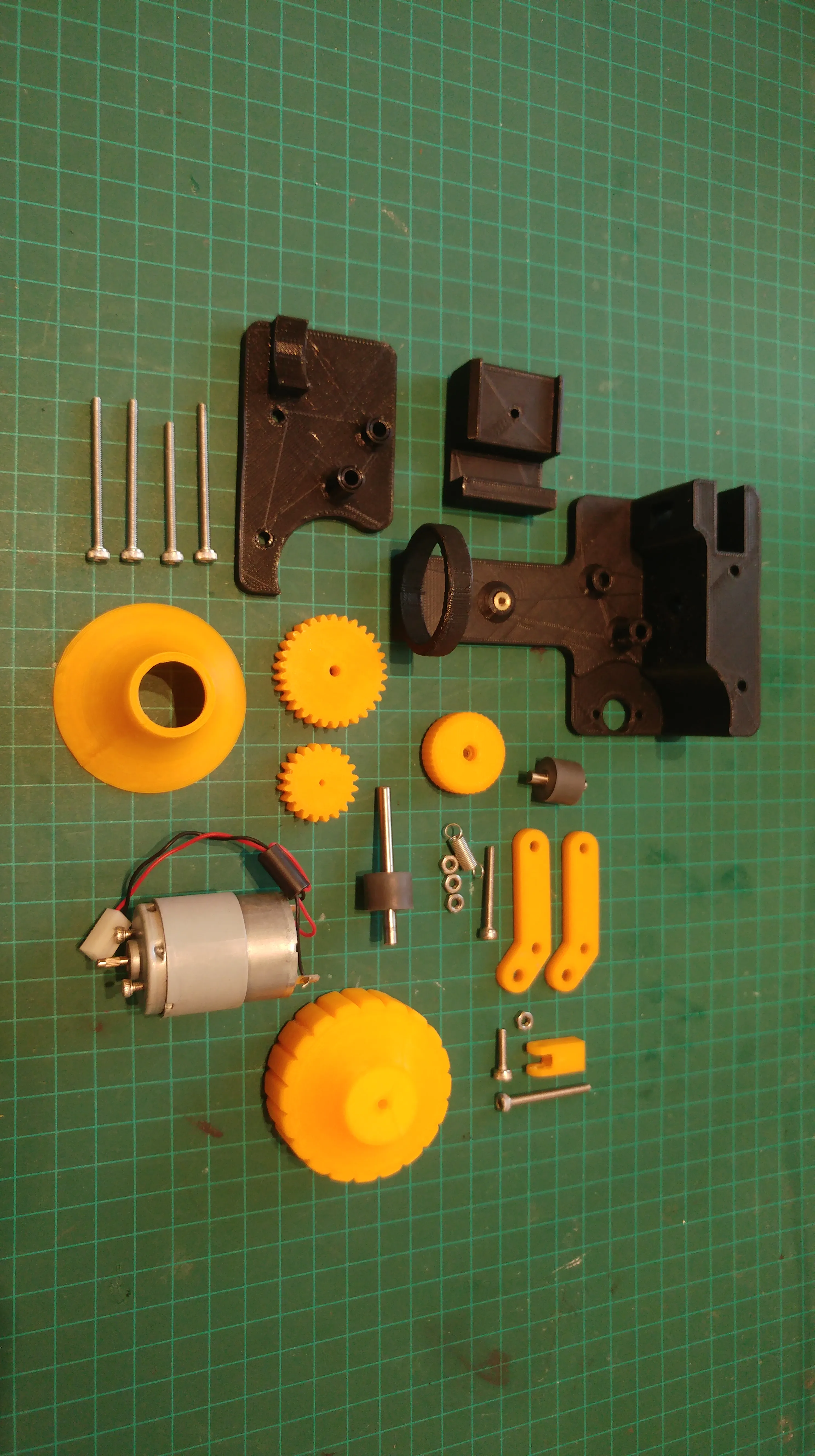
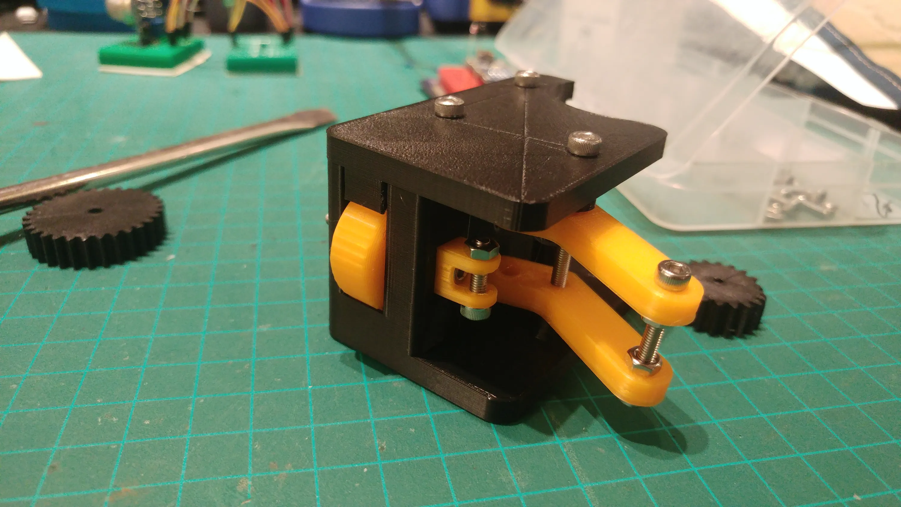
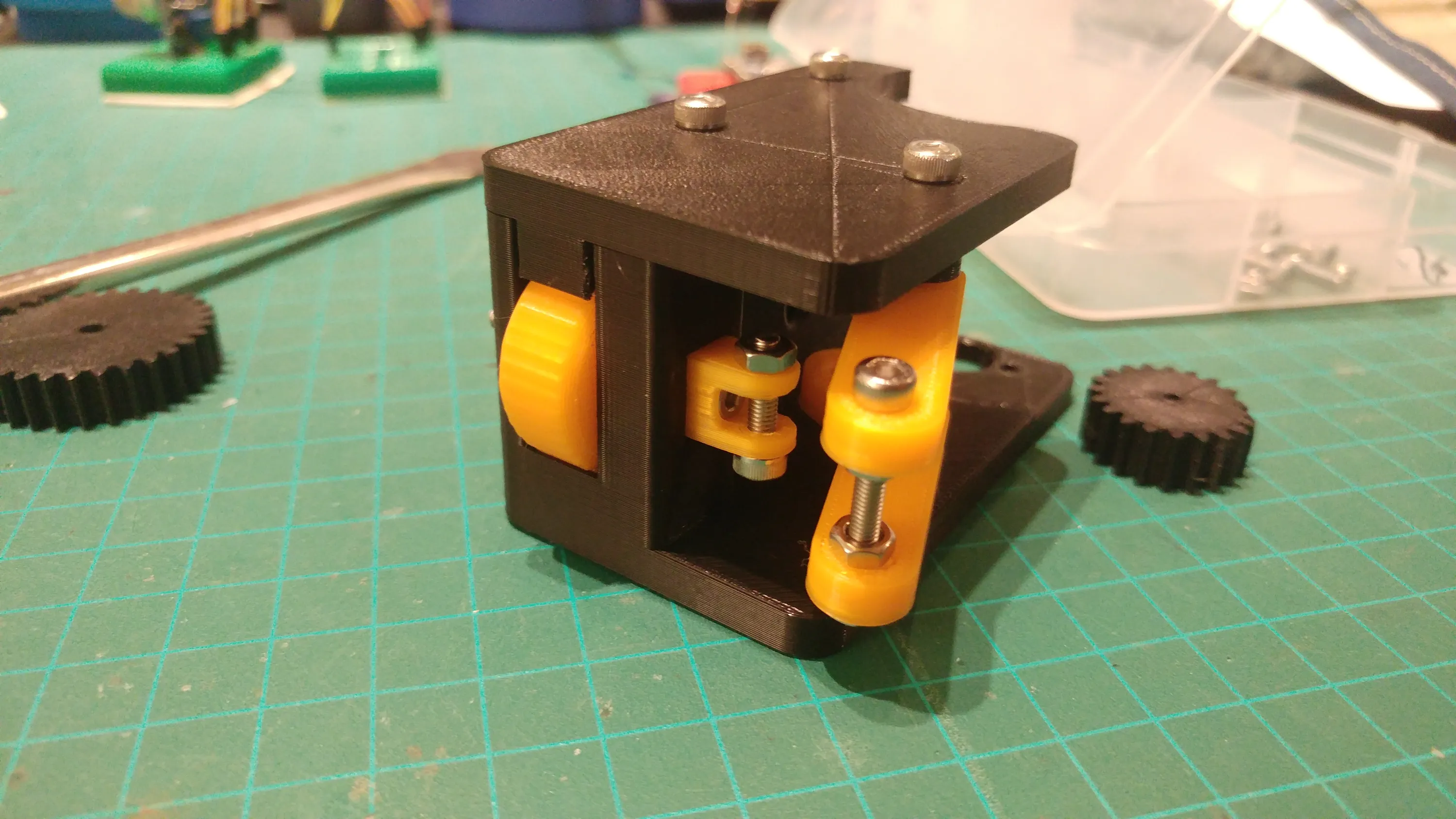
One of the rubber cylinders is spinning free and the other is driven by a motor (which was also salvaged from the same printer).The motor’s speed is reduced slightly by the gears.Some silicone grease was applied to the gears to help reduce wear and noise.
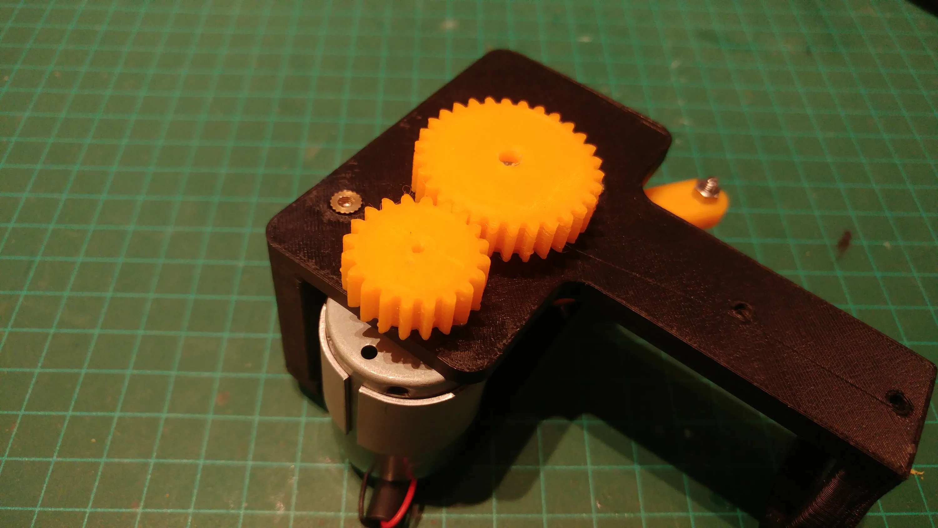
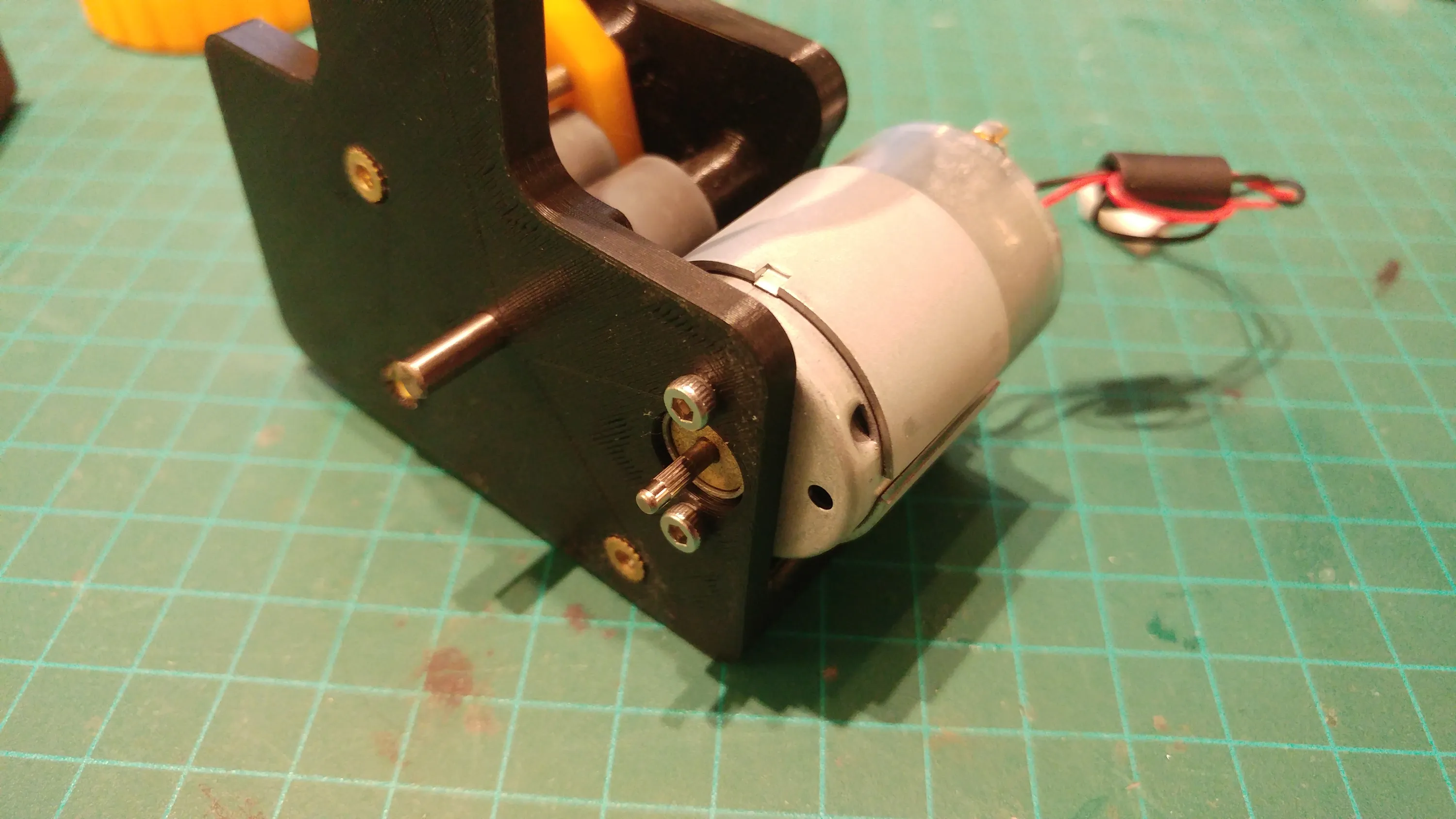
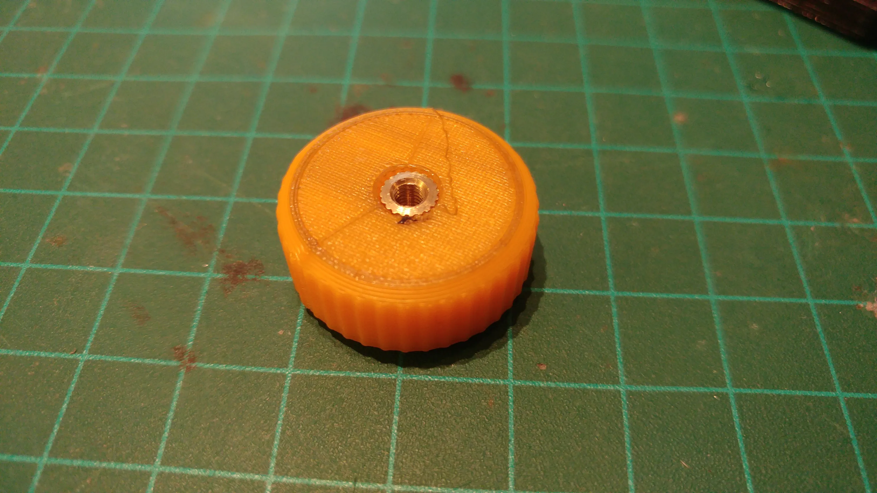
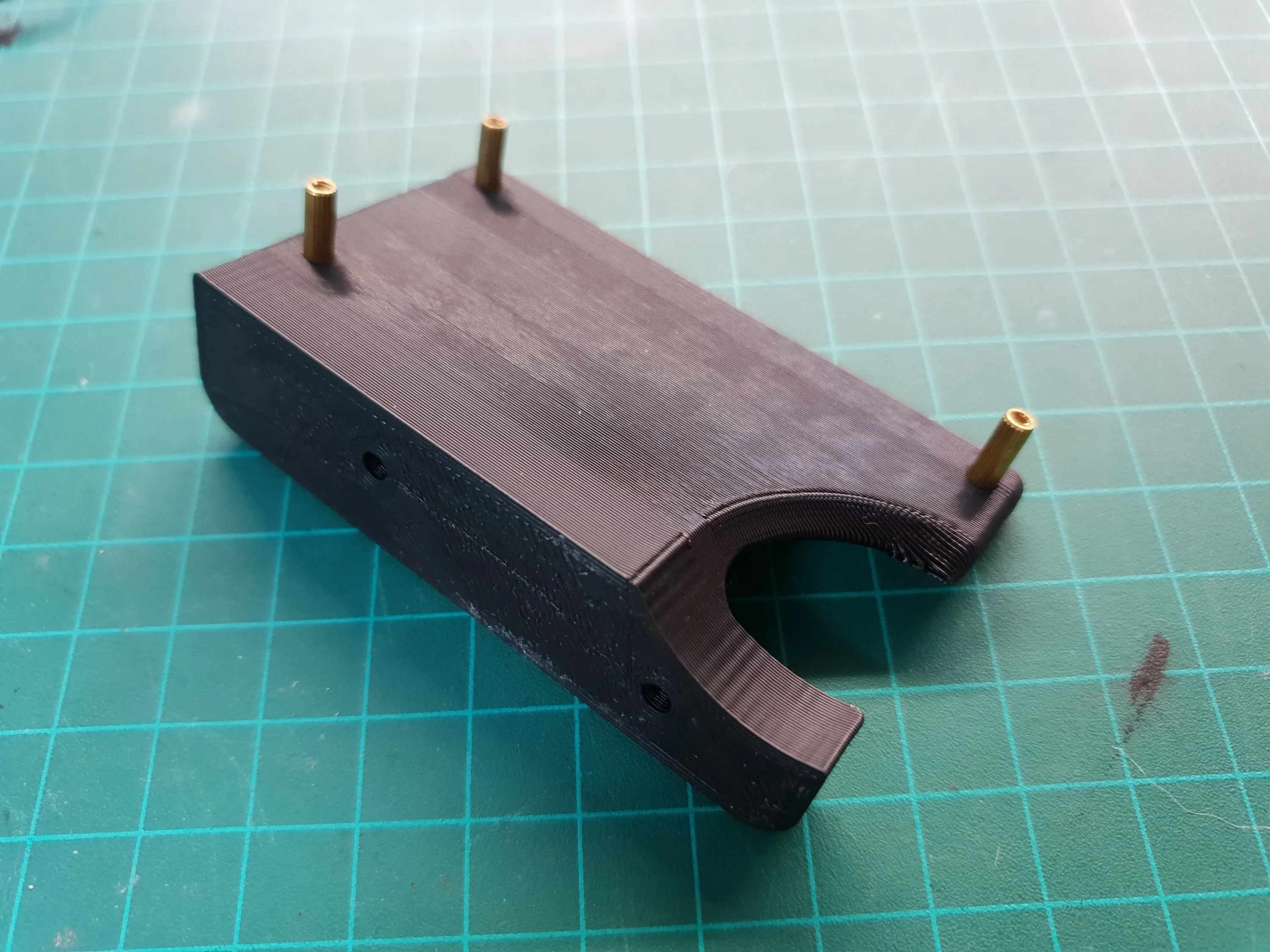
All screws fit into knurled nuts that are embedded into the plastic with heat.
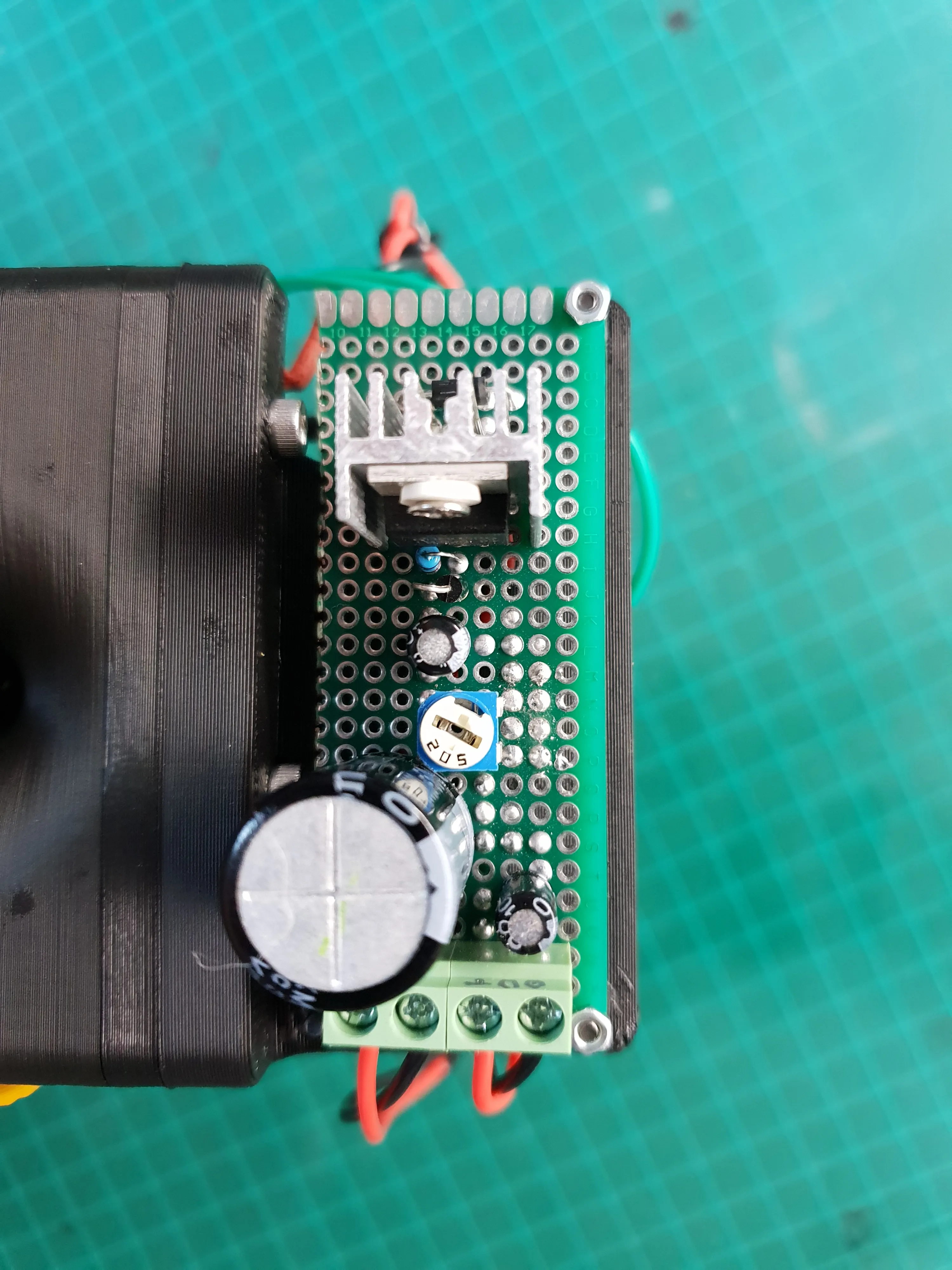
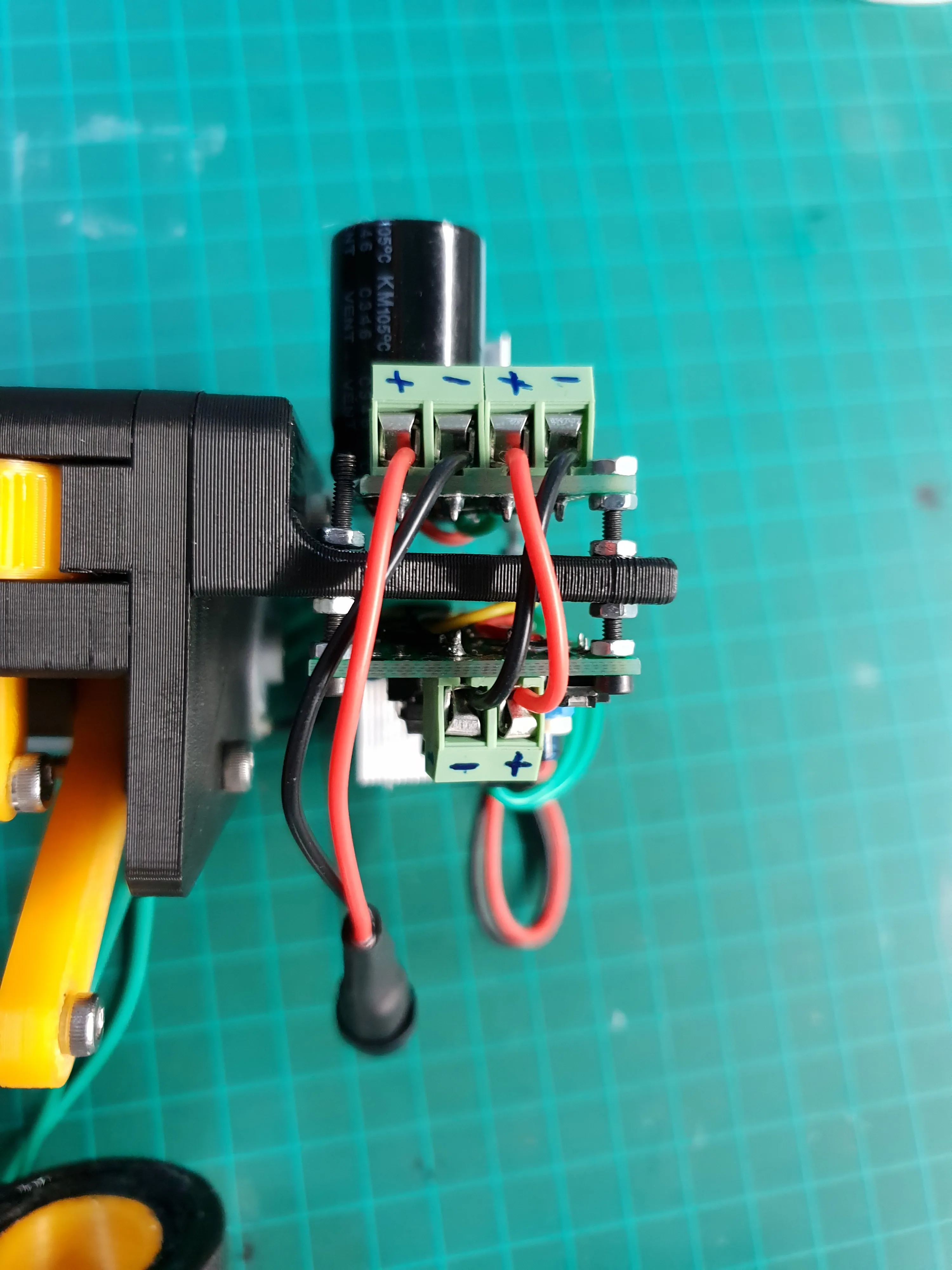
The Circuit
What I want the circuit to do is drive the motor for an adjustable amount of time at an adjustable speed after it’s triggered. pretty simple.I can use an Arduino with bit of code to make it work, but I figured this can be done with a purely analog circuit.I also preferred that the operation will be independent from the printer. No need to start taking signals from the driver board or talk to Octoprint.
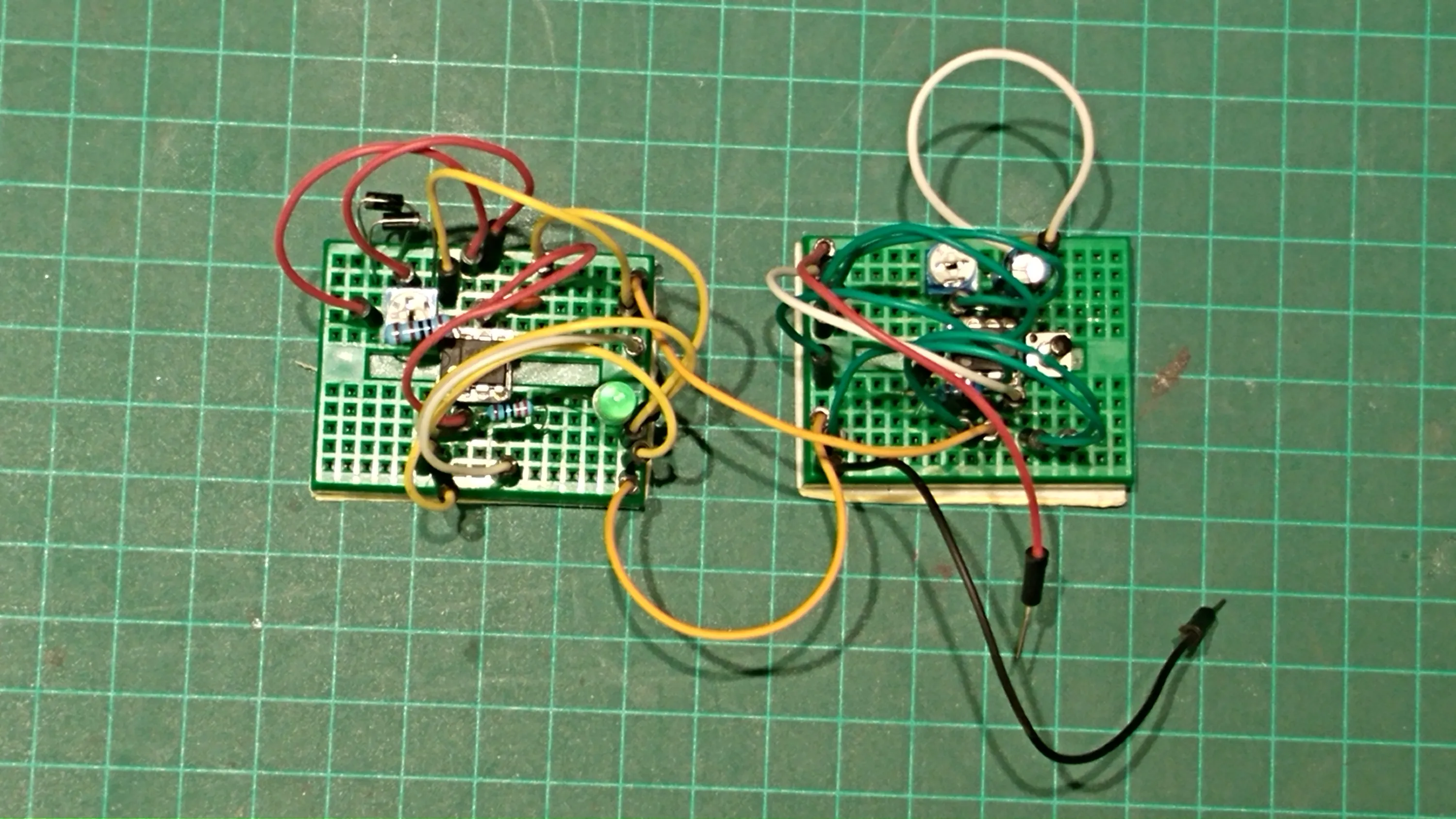
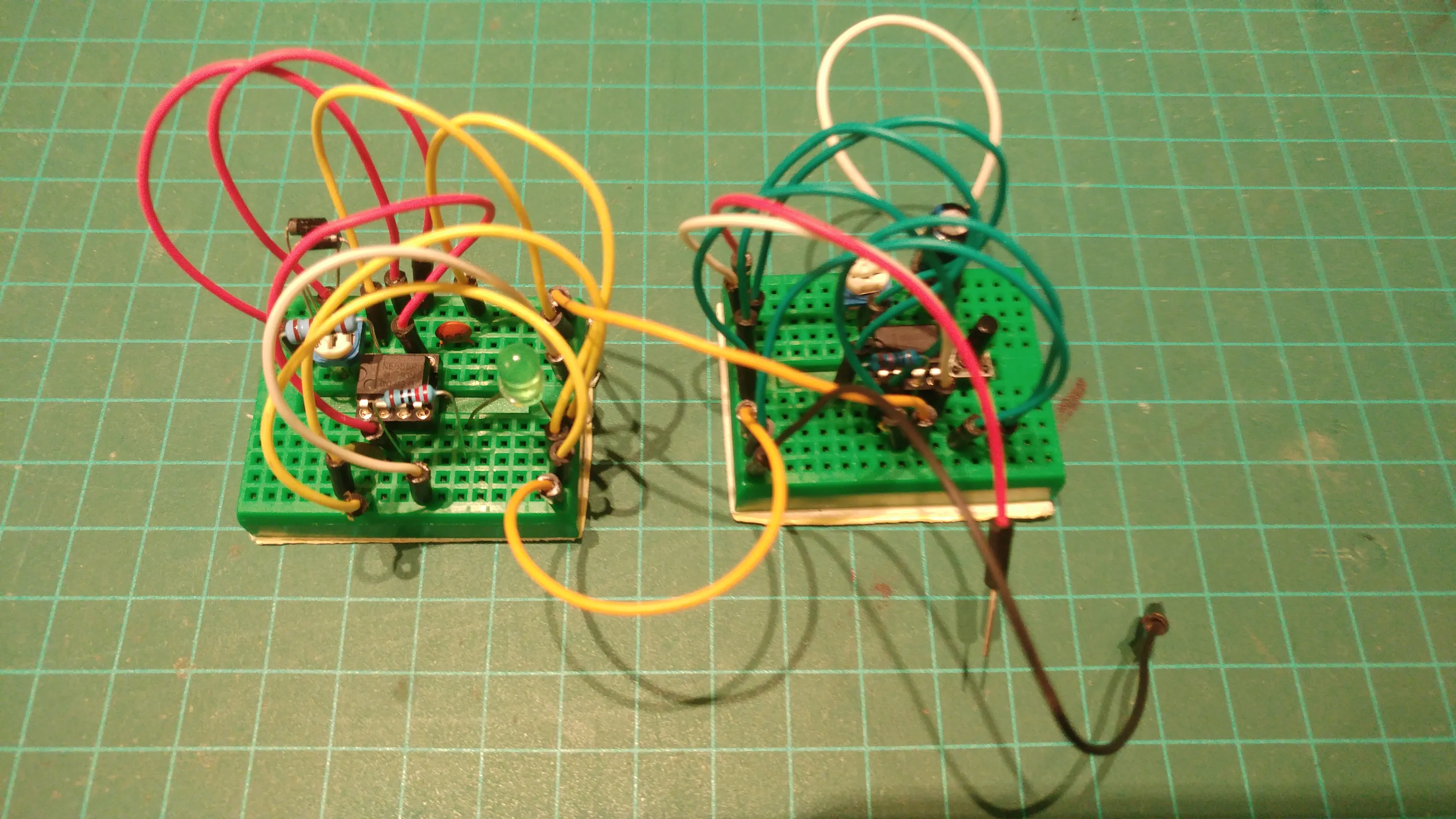
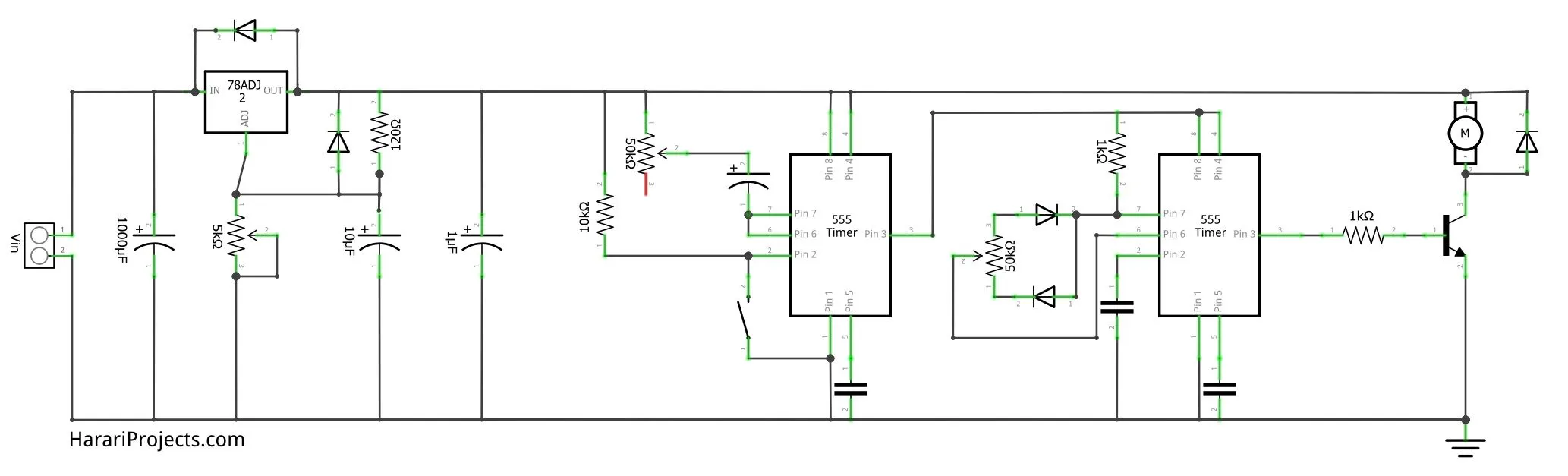
I went with a couple of 555 timers to get the functionality I want.The first 555 timer is configured in a “delayed off” configuration. While it’s trigger is HIGH, the output is HIGH. When the trigger goes LOW, the output stays HIGH for a time determined by the potentiometer and then returns to LOW.The output of the first 555 timer powers the second 555 timer.
The second 555 timer is configured as a PWM driver to control the speed of the motor. It generates a PWM signal while it has power.The PWM frequency and duty cycle are controlled via the potentiometer. (The frequency is not really relevant to the application, but making it static while the duty cycle changes is more difficult).
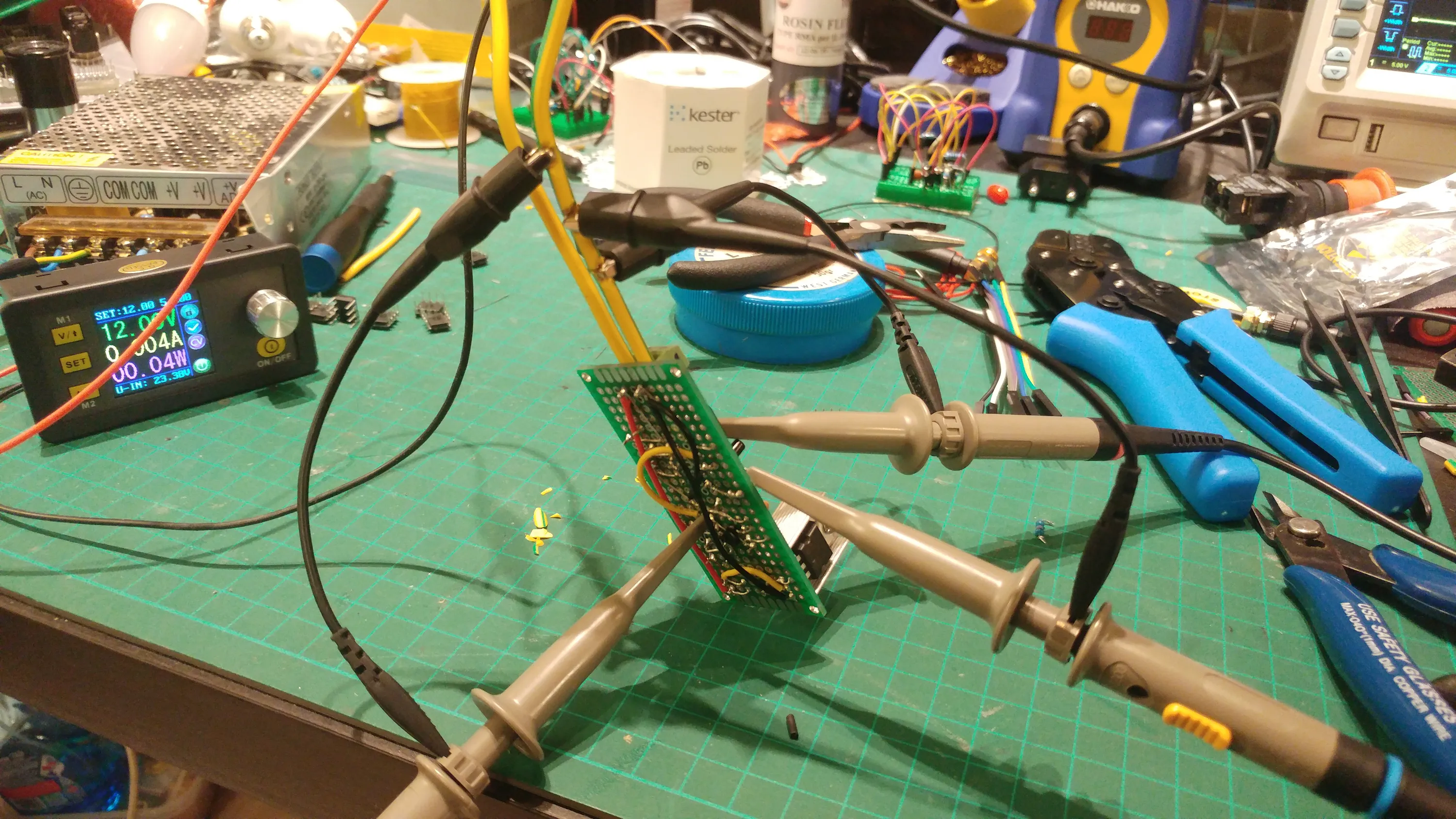
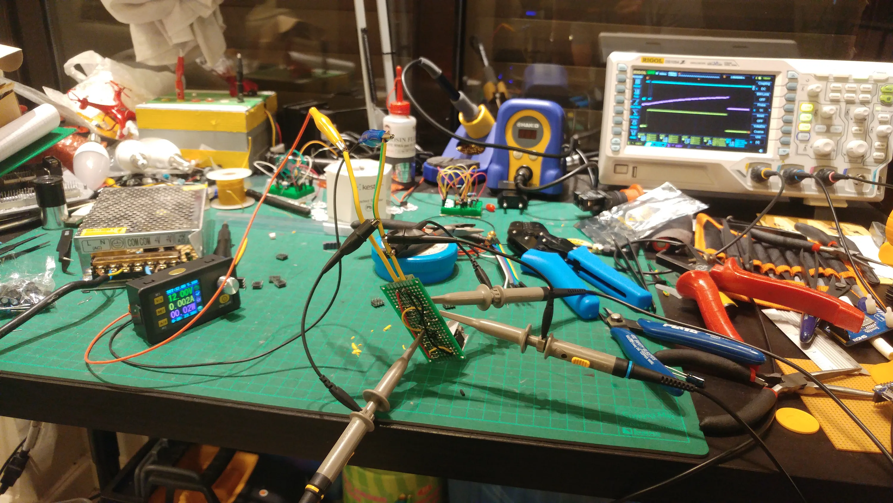
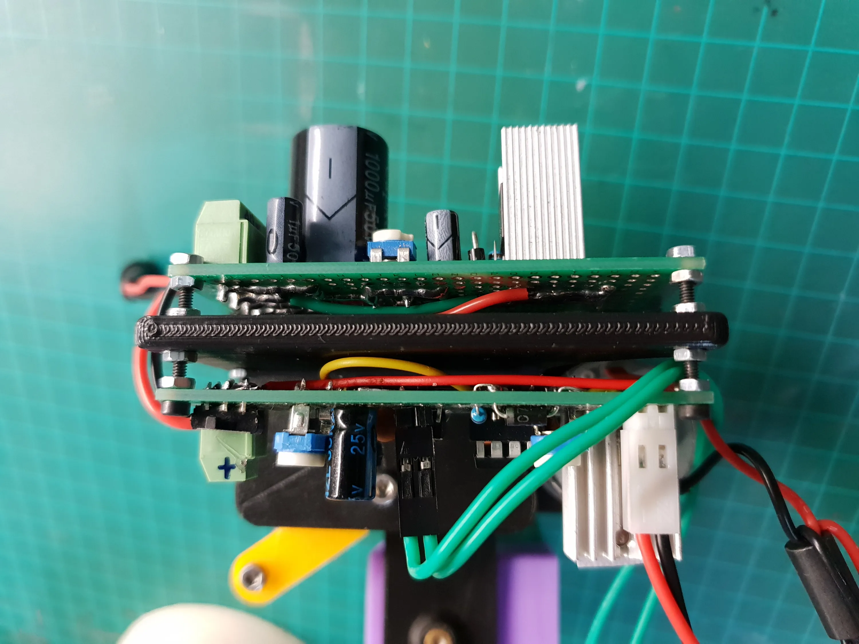
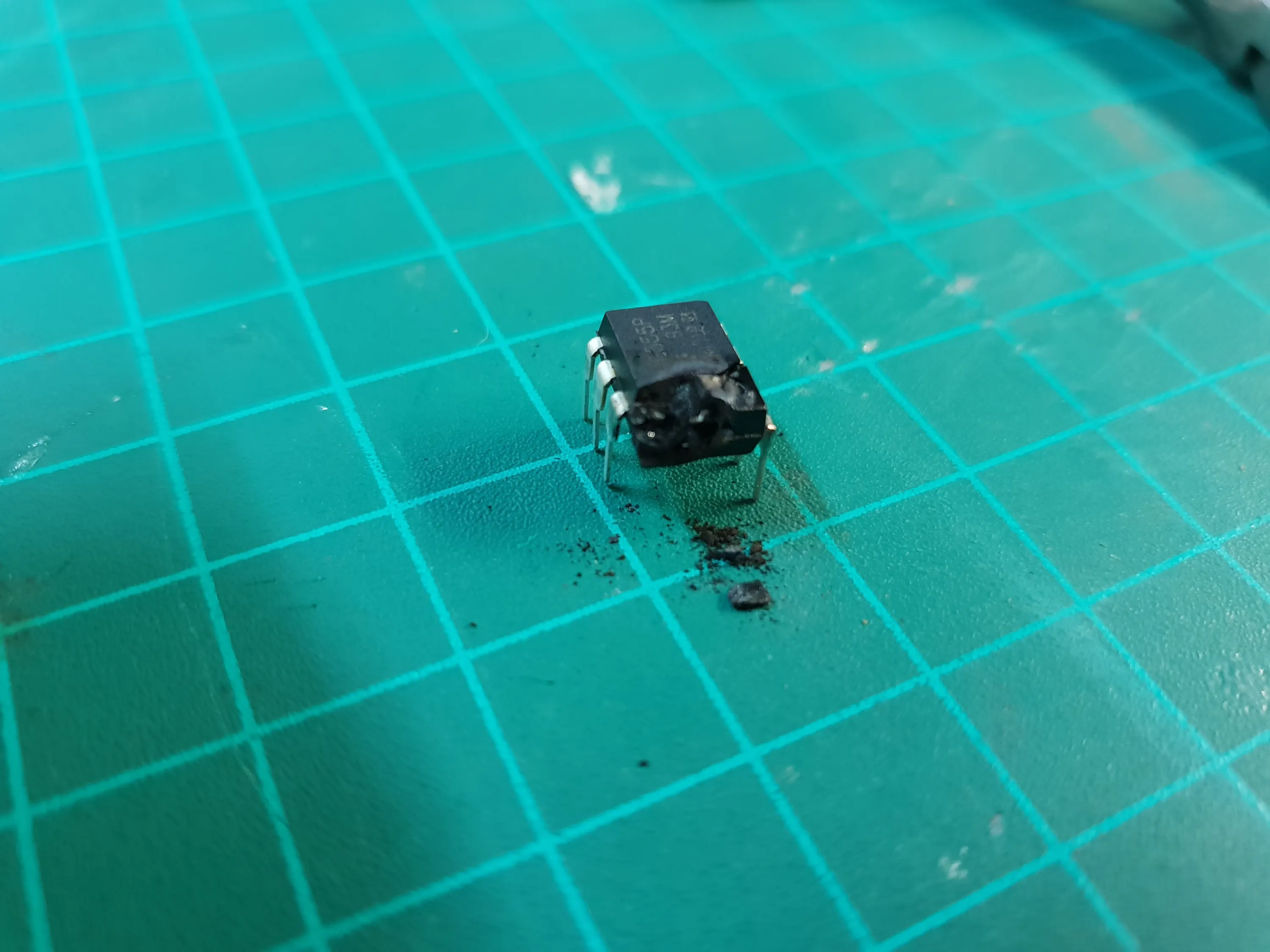
After a few experiments, I realized that 12V from the printer’s power supply is too much and under load I would occasionally fry the first 555.To address the issue, I added a LM350T regulator with an adjustment pot to limit the voltage. I found that around 7V works nicely.I also printed a piece to mount the circuit to the main body.
Here is the schematic for the circuit:
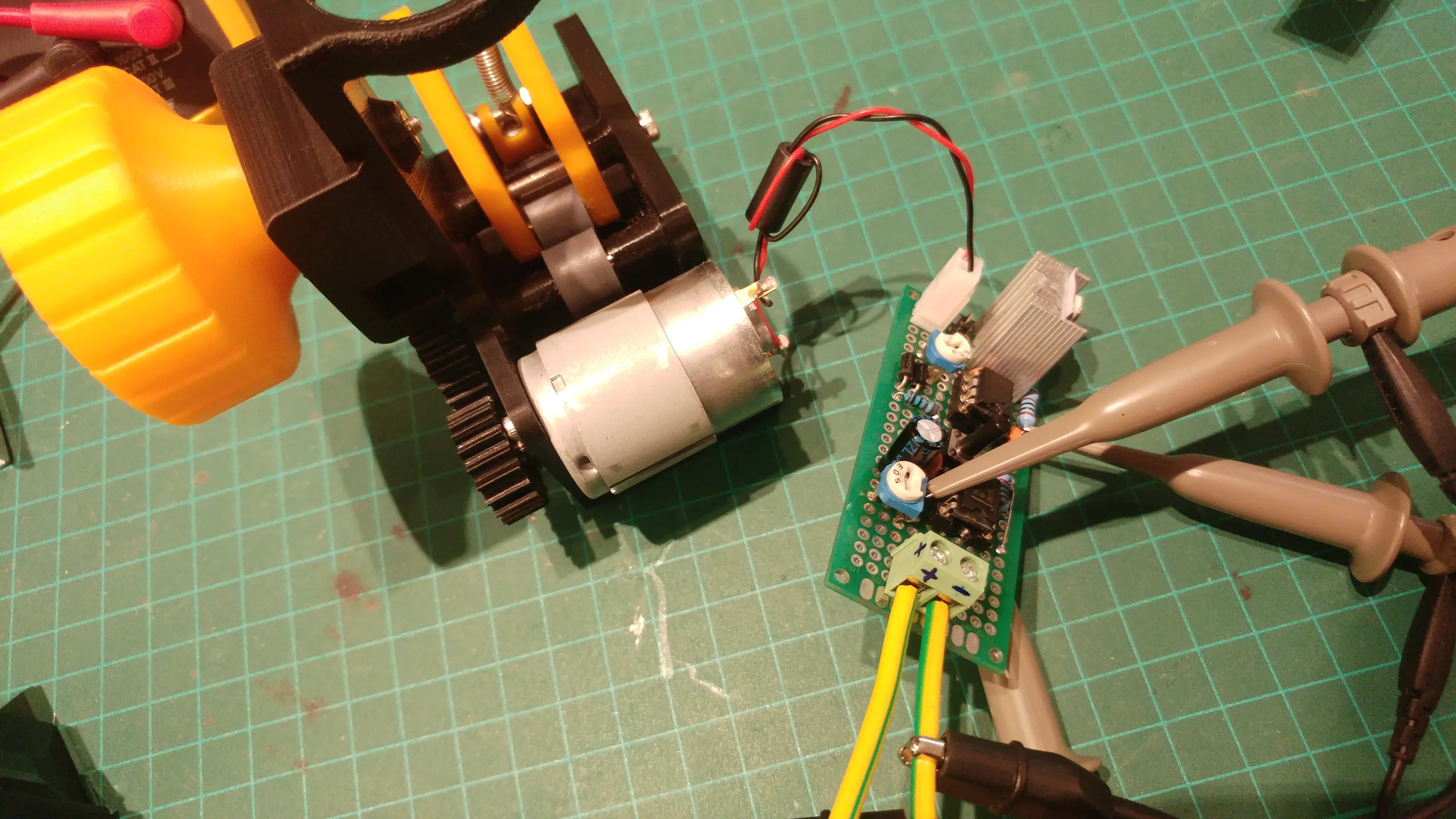
The trigger
Driving a motor is pretty straight forward, but how do I detect that the printer is pulling on the filament?
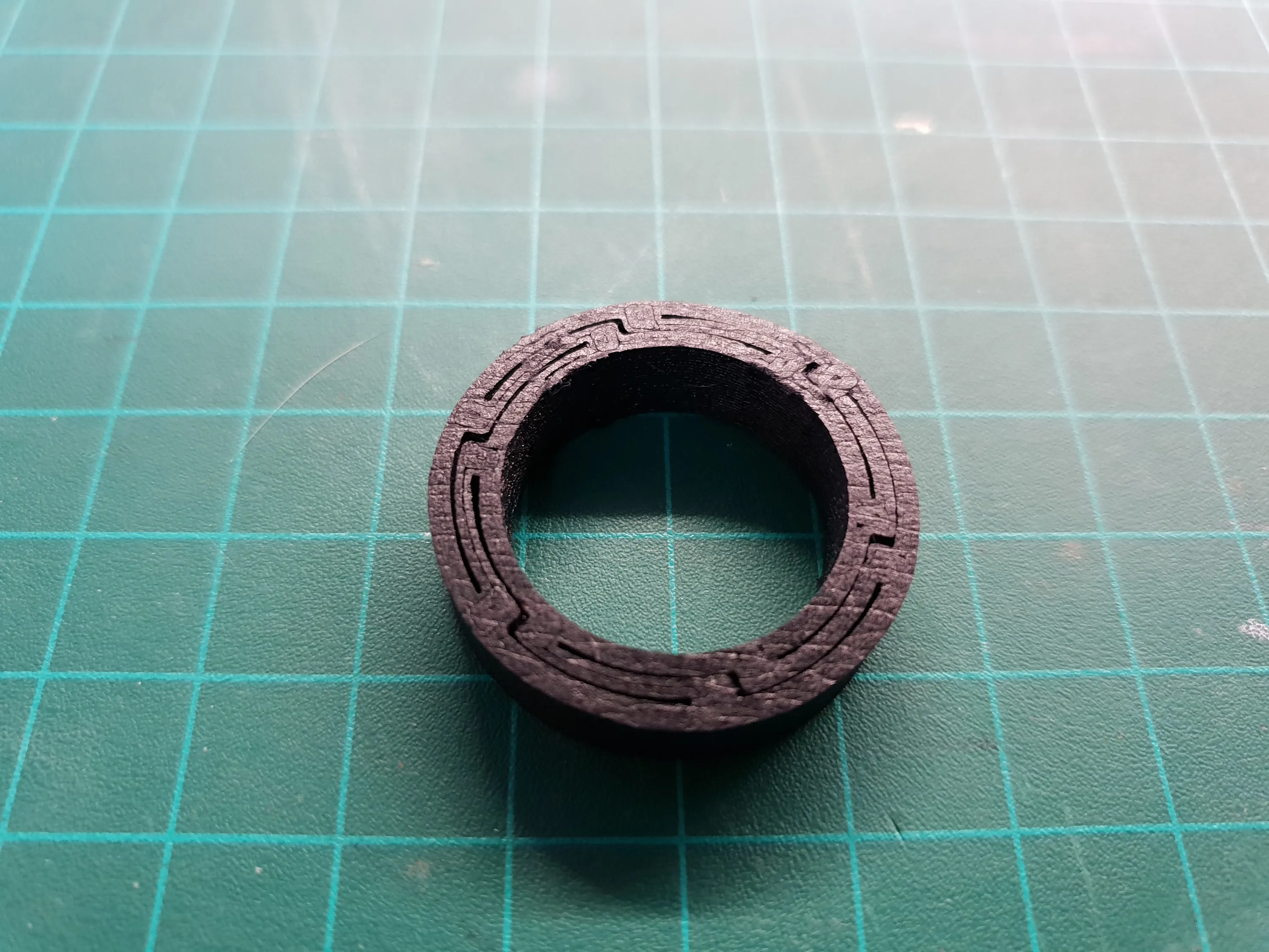
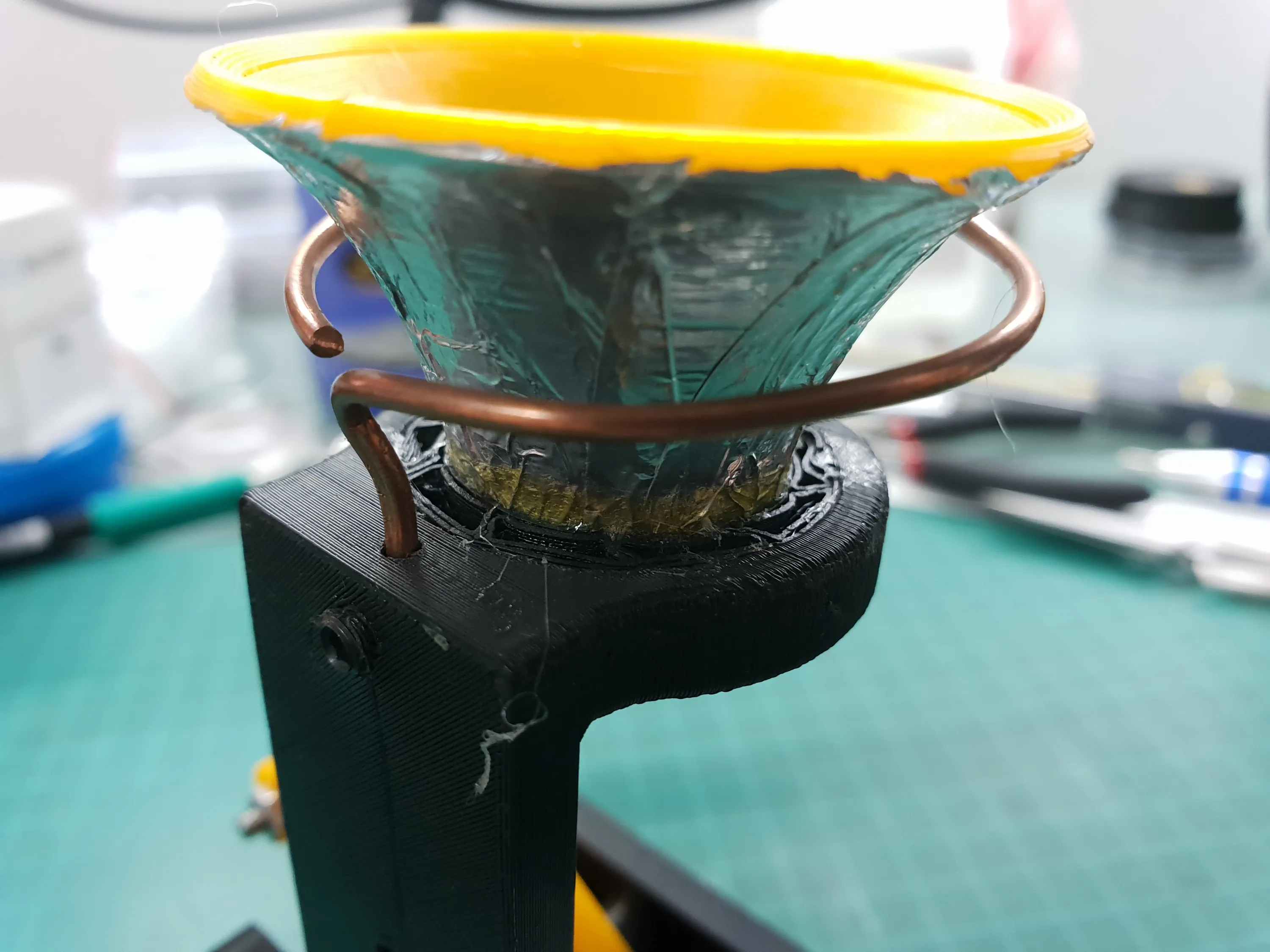
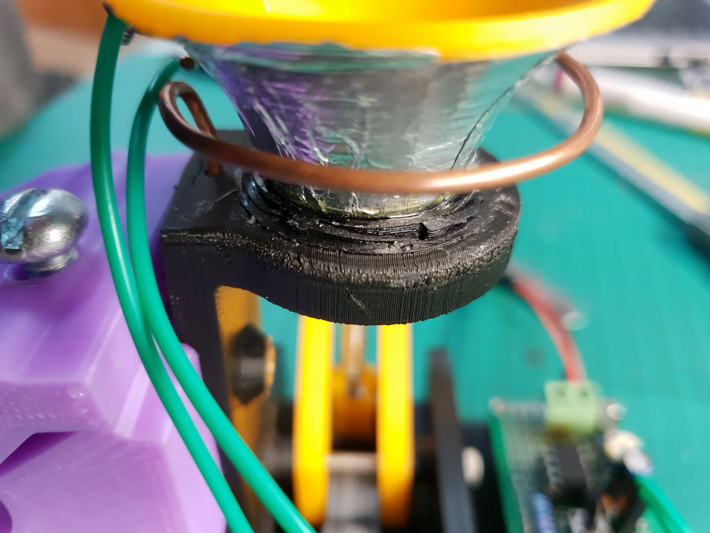
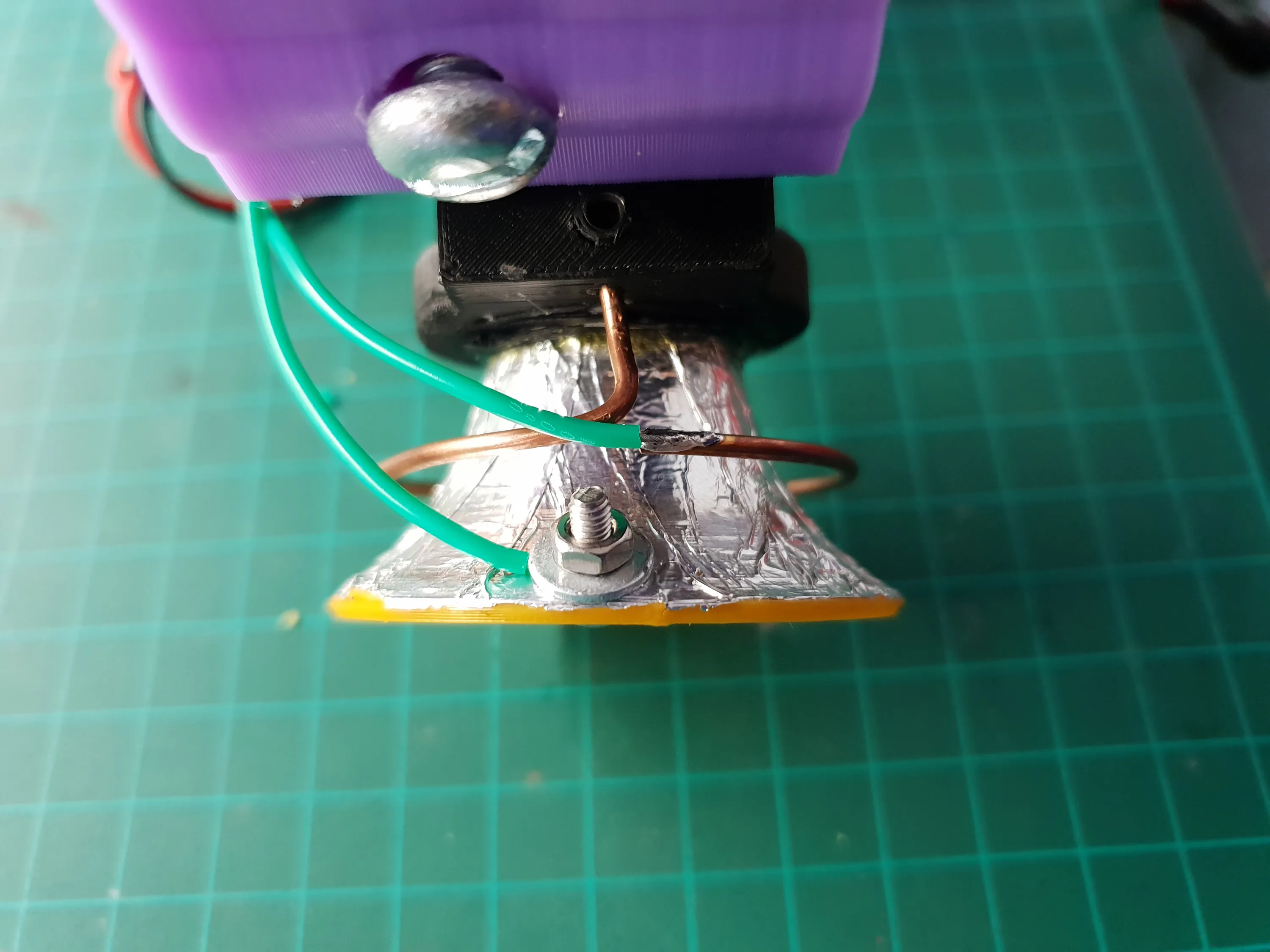
I thought about all sorts of sensors and complicated ways to turn it into a trigger, but I wanted a simple and reliable solution.What I came up with is a copper ring and a tapered cone that’s conductive on the outside. The cone is suspended in the center of the ring so when the filament is pulled, the cone touches the ring and closes a circuit that triggeres the first 555 timer.
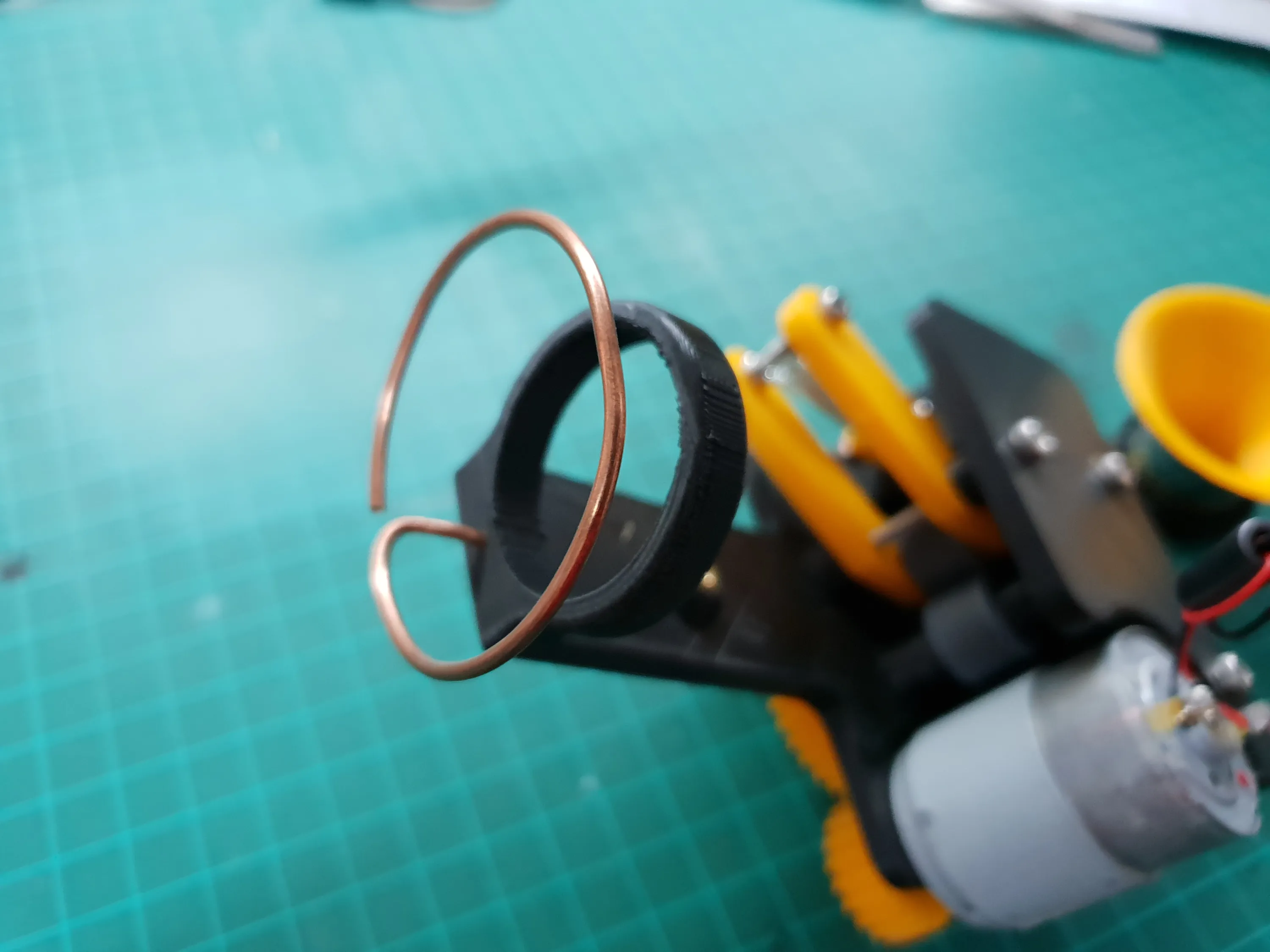
I tried a few different techniques for holding the cone while allowing it to move and return to center, from different foams to strings and springs.The project spanned over a long enough amount of time that my printer has had some upgrades by the time I got to this part. In the end, I used flexible filament and a structure that would allow more flex in the small thickness of the part.
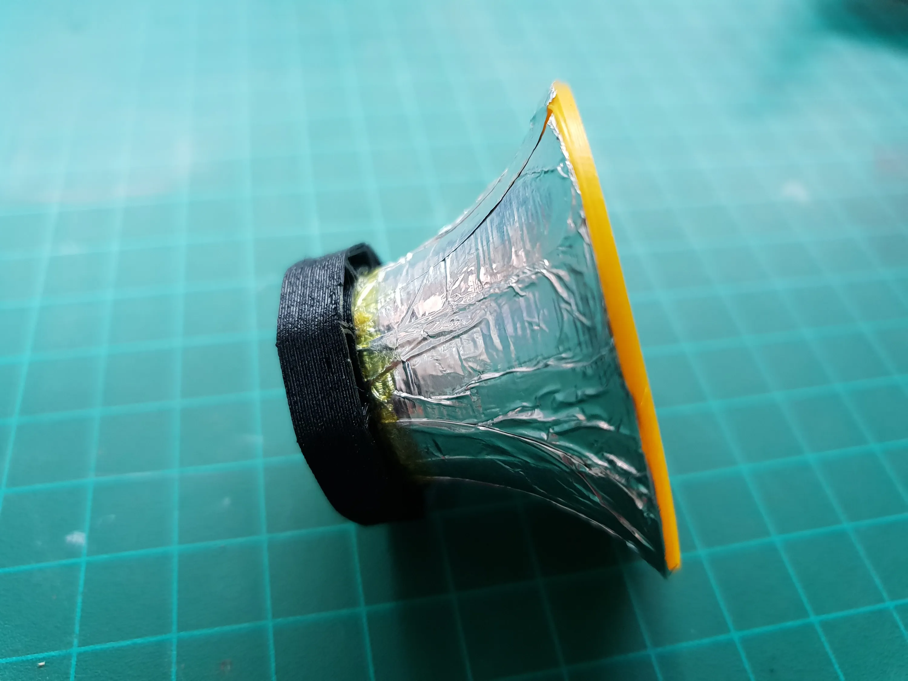
Soldering a wire to the copper ring was easy, but the aluminium tape wouldn’t take solder at all. I had to drill a hole and clamp the wire to the cone with a screw and washer.
Mounting
As I mentioned, the project spanned over a pretty long time and by the time I finished, the printer moved to a new location and the mounting method had to change.
At first, I wanted to have an aluminium square tube that would be held at both ends and clamped between the body of the device and an additional bottom piece.
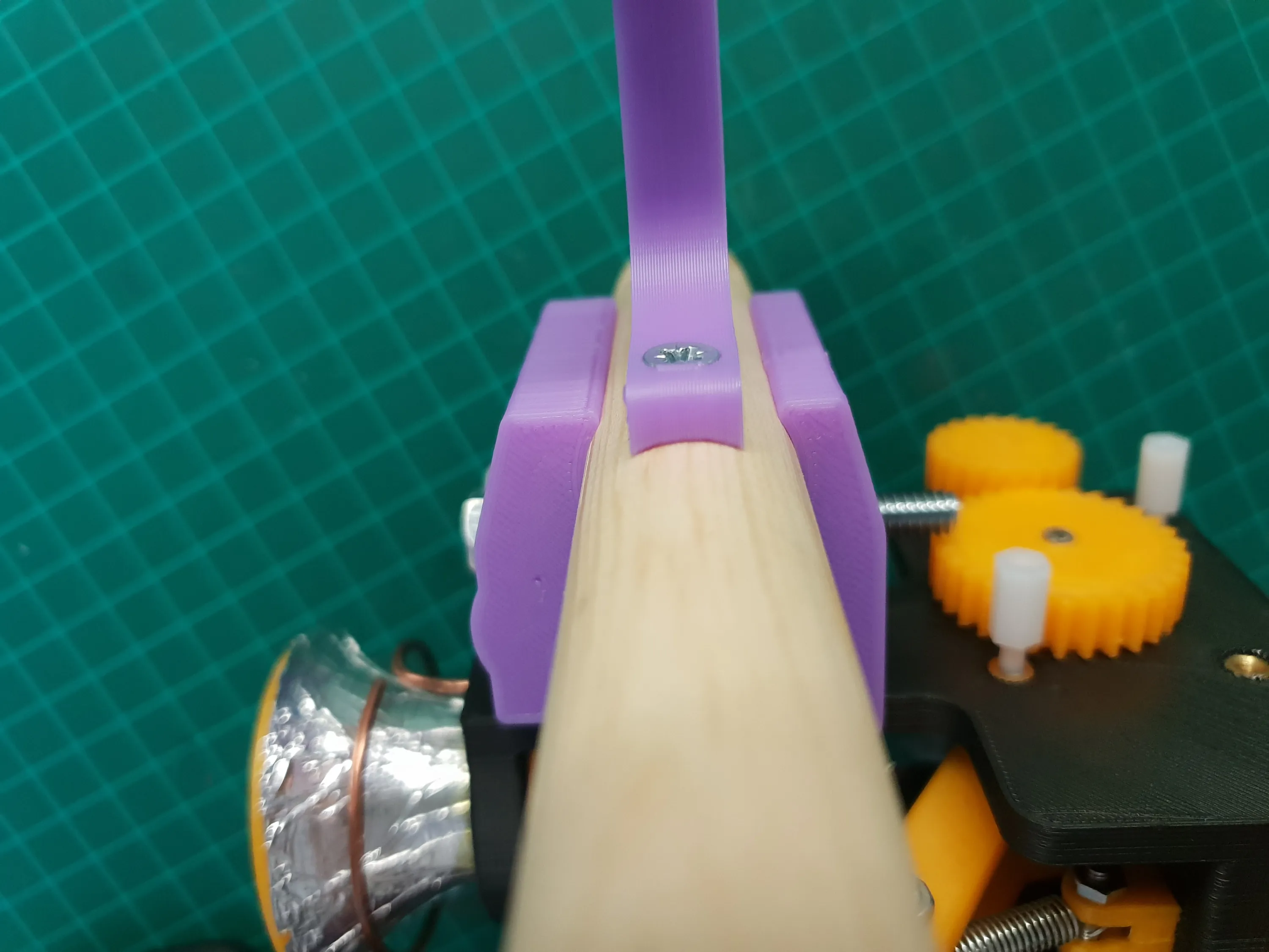
In the printer’s new home I needed a longer rod and it had to be held in the middle without blocking the movement of the clamp to the other side of the rod.I decided to go with a wood broom stick as the rod and I mounted it form the top with screws and a printed bracket.
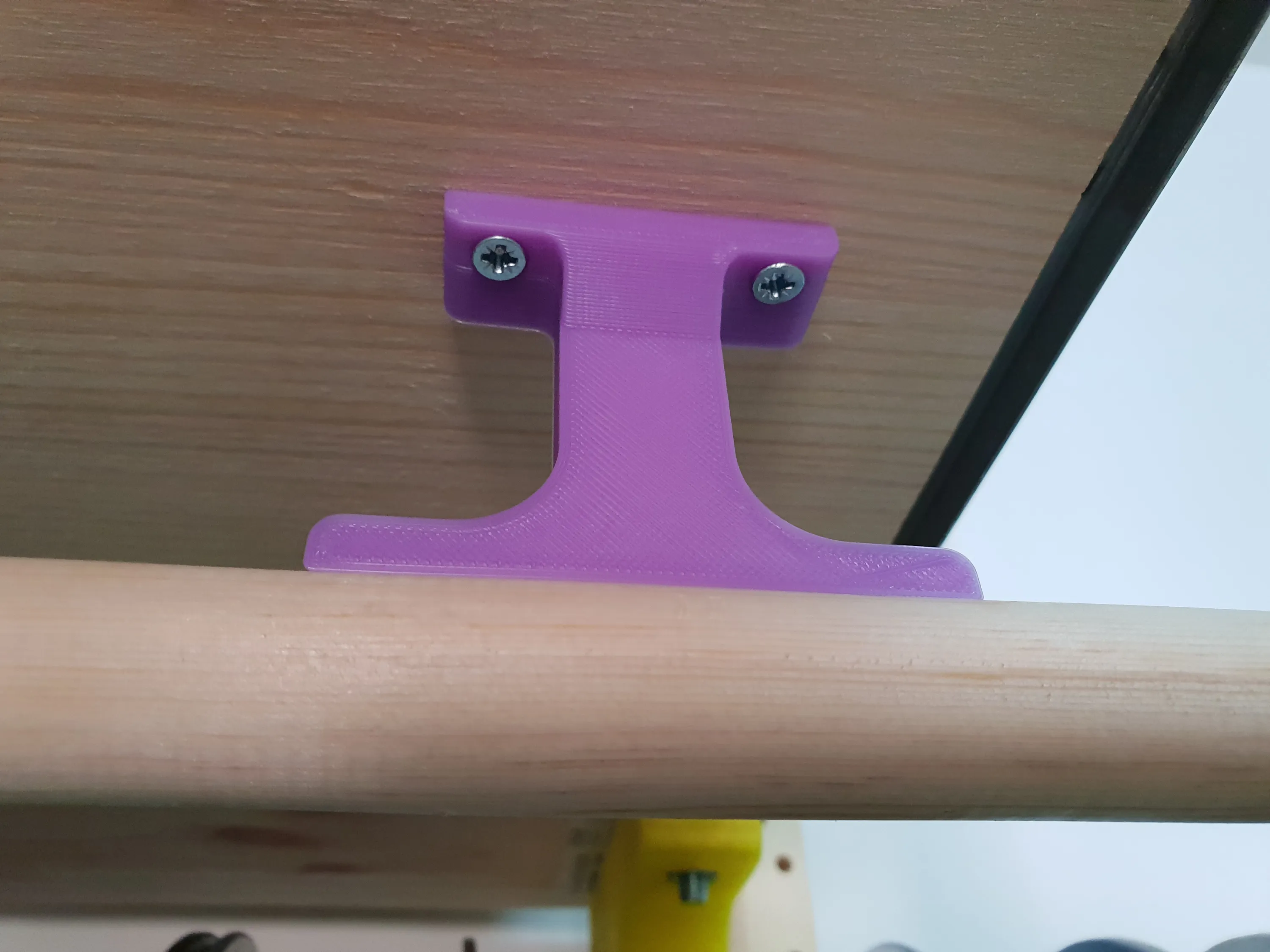
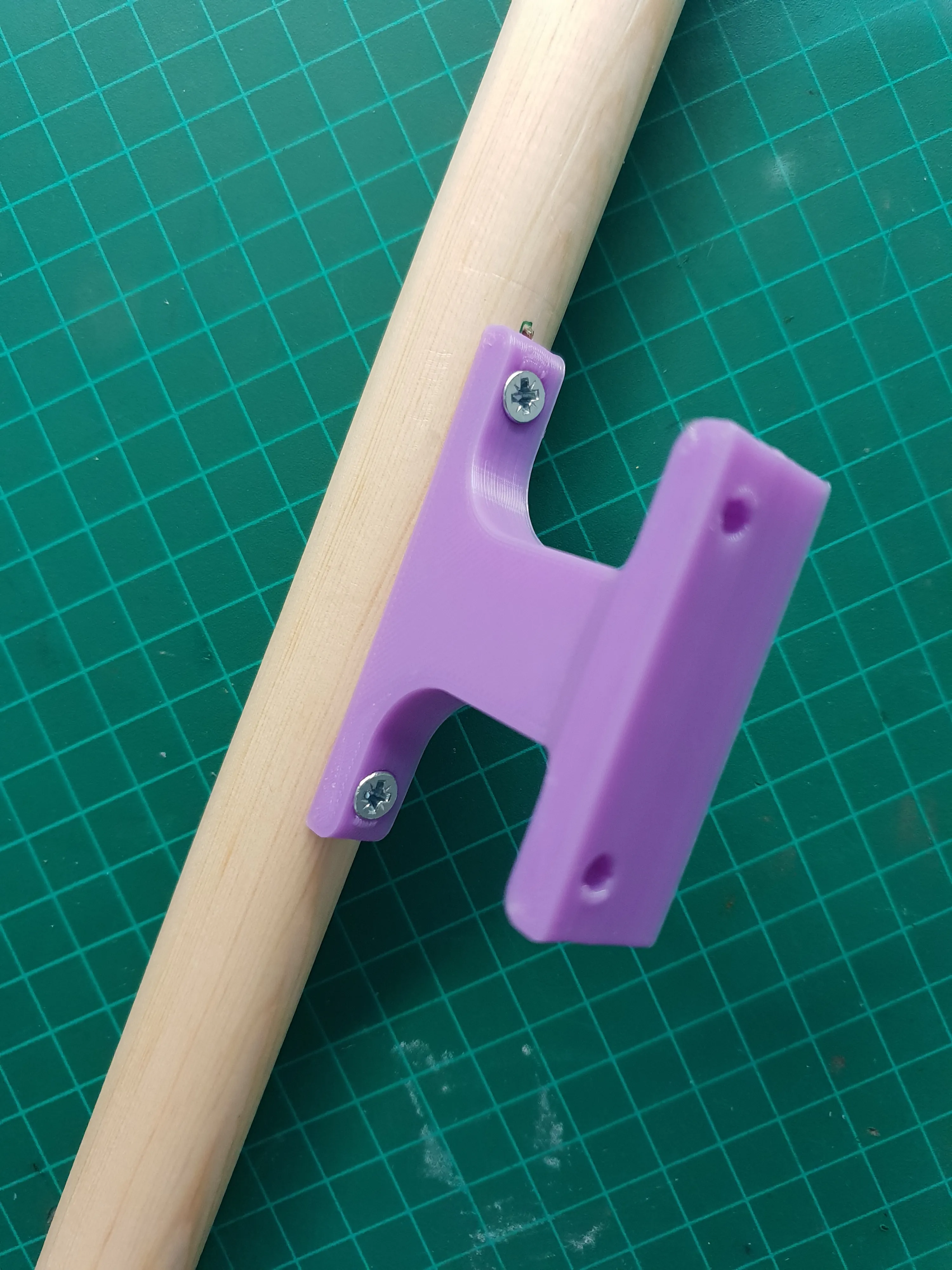
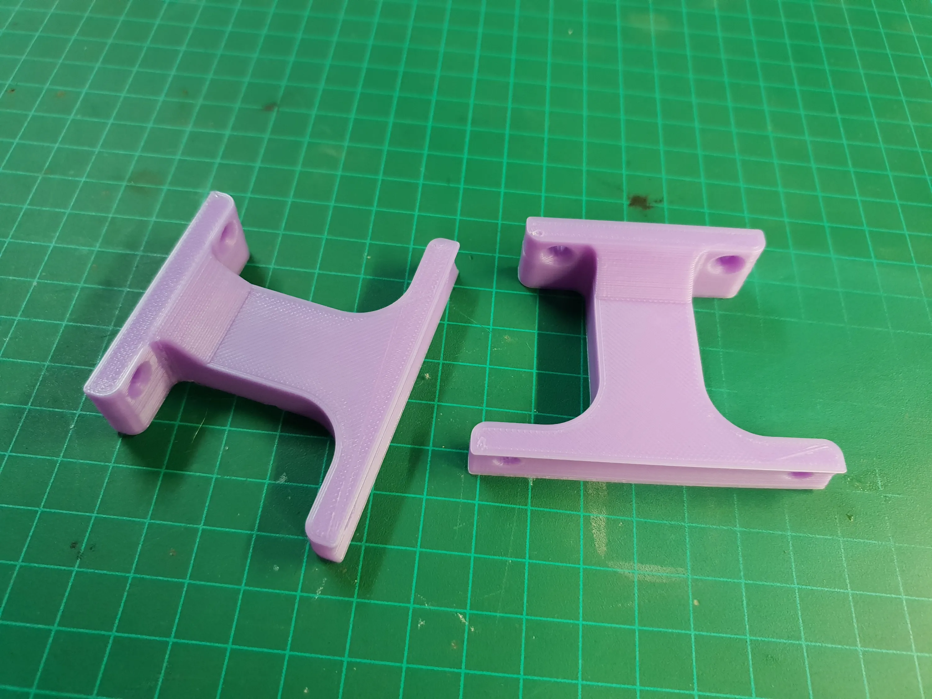
To allow the clamp to slide past the bracket, I clamped the rod on the sides instead of from the top and bottom. This also made the clamp independent from the rest of the body and made it modular so that I could change the clamp if I ever replace the broom stick.
https://videopress.com/v/JDWobFXC 20190205_221844.mp4
Now, after this is all done and working, it’s time to make another one for my second extruder..
As usual, the files are available for free on Thingiverse.