For the last Purim festivities I made a Sims Plumbob that’s controlled via an android application through Bluetooth to simulate the Sim mood.
In this article I’ll show you what I’ve done and why so you can make one yourself.
The Plumbob
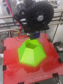
The Plumbob itself was 3D printed. The shape is very simple and it can be modeled very easily, It’s just two hollow hexagonal pyramids glued to each other.
Lazy me didn’t want to start modeling so I found a pre-made model on thingiverse. The shape was perfect and I had the perfect material for the job – a translucent green PLA filament. I chose this material because I wanted to put lights inside that would illuminate the Plumbob in different colors, the material was translucent enough for colors to penetrate and be seen at night and it was green so it would be recognizable in the day, when the lights are not very visible.
The downloaded model has a stem on one side, but it’s not hollow (I needed a stem to mount the Plumbob and it needed to be hollow for electrical wires to go through it). I needed to drill through the stem, which is not an easy task, I ended up breaking it and using another method to secure the Plumbob to its mount.
The Plumbob was printed out of Translucent Green PLA at 190 degrees C. 0.3mm layer height and 100% infill. The print took about 3 hours for each half.
The Mount
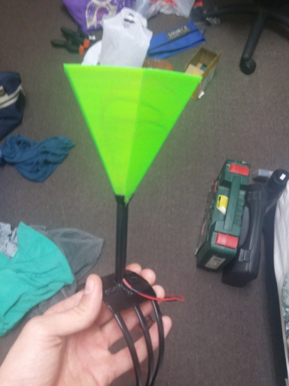
I needed a way to mount the Plumbob a few inches from my head, I wanted it to look at night as if it was floating, like in the game. I figured a hair bow with a rod on top painted black could do the trick.
I needed a wide bow for stability, a narrow or thin one would just fall from the weight and movement. I thought about 3D printing a custom mount but I didn’t have enough time to measure, model and make one so I went to the nearest store and tried some bows on.
I didn’t find a wide enough bow, but I found a bow that looked like three bows connected at both ends, it was flexible enough so I can pull them apart to make the whole structure wide enough. Moreover, when I pulled them apart the entire structure was stiffer, less flexible, which is exactly what I needed.
On top of the bow I put a piece of tin I cut to shape with some tin sheers, the tin provides a strong base for the stem and will hold the stretched bow parts in place. I used two part Epoxy glue for all connections.
The stem is an aluminium tube cut to length with the ends split and bent to follow the contour of the hexagon pyramid to be attached to it on one side, and the tin base plate on the other.
Before gluing the Plumbob half to the stem, I spray painted the whole thing black.
Electronics
I used RGB LEDs for lighting and a 5V Arduino pro mini for control. The Arduino supports about 40mA of current draw from each pin and the LEDs are common Anode and draw about 20mA per color (I used 6 LEDs, that’s 120mA total current for each color of all LEDs on full brightness), so I had to use 2N3906 transistors to switch power to the LEDs (I could have connected each Cathode of each of the LEDs to another pin in the Arduino to avoid the current problem, but the Arduino doesn’t have enough PWM pins and that would require me to modify the code).
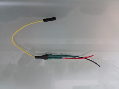
To save space on the circuit board, I shortened the Cathode leads of the LEDs and 150Ohm resistors and soldered them together inline.
To make life easier, I made a jig by fixing a 5mm LED bezel with vice grips, this made soldering very easy.
I used a HC-05 Bluetooth module for communication and a U1V11F5 5V step-up converter so I could power the whole thing with 2xAAA batteries.
The Bluetooth module operates at a 3.3V logic level while the Arduino operates at 5V, the arduino would understand the 3.3V from the Bluetooth module fine, but 5V to the Rx pin of the module could fry it. for this I connected the module’s Rx pin to the Arduino’s Tx pin via a voltage divider (a dedicated logic level converter circuit would have been ideal but I didn’t have one nor did I have time to wait for one to arrive).
The circuit had to be mounted to a post made of aluminium tube, so I had to insulate the tube to prevent shorts. The circuit was held in place with zip ties, the LEDs were wrapped around and hot glued in place so that they point in different directions to illuminate the whole shape (in retrospect, I could have used shorter leads for the LEDs).
The aluminium tube was held in place with hot glue and then secured with Epoxy.
The battery holder was mounted on the stem for lack of a better place to put it. I thought about putting it in my pocket with wires running inside my shirt, but they proved to be too long and the resistance was too high so the Arduino would reset when the current draw was high and the voltage dropped.
I needed the batteries on the outside because the power switch was on the holder and I wanted to be able to change batteries. If I had more time I would have probably installed a rechargeable li-po battery inside the plumbob with a small switch and a charging port poking from the side.
The Code
I didn’t have time to write an android application, so I found a free one on the Play Store that fit my needs exactly. There are a lot of applications that do similar things and much more, but this one had a friendly interface and did just what I wanted.
In the description of the app there’s a link to a free example code (and a full code for purchase). I used the free example and modified it to fit my setup.
I also had to use the Software Serial library because, for some reason, the Bluetooth module refused to work with the Arduino’s Serial pins. I used pins 10 and 11 for serial communication with the module (this also allowed me to upload sketches to the Arduino without disconnecting the module).
//pins for the LEDs:
const int redPin = 6;
const int greenPin = 9;
const int bluePin = 5;

#define REDPIN 9
#define GREENPIN 6
#define BLUEPIN 5

#define FADESPEED 5

char serialByte = '0';

#include <SoftwareSerial.h>
SoftwareSerial BTserial(10, 11); // RX | TX

void setup() {
// initialize serial:
BTserial.begin(9600);
Serial.begin(9600);

// make the pins outputs:
pinMode(redPin, OUTPUT);
pinMode(greenPin, OUTPUT);
pinMode(bluePin, OUTPUT);

Serial.print("Arduino control RGB LEDs Connected OK ( Sent From Arduinno Board )");
Serial.print('\n');
}

void loop() {

// if there's any serial available, read it:
while (BTserial.available()) {

// look for the next valid integer in the incoming serial stream:
int red = BTserial.parseInt();
// do it again:
int green = BTserial.parseInt();
// do it again:
int blue = BTserial.parseInt();

for(i=0; i<3; i++)
{
int waste = BTserial.parseInt(); //the app sends data for two sets of LEDs, we don't need this
}
// look for the newline. That's the end of your
// sentence:
if (BTserial.read() == '\n') {

// constrain the values to 0 - 255 and invert
// if you're using a common-cathode LED, just use "constrain(color, 0, 255);"

// This is for COMMON ANODE
//red = 255 - constrain(red, 0, 255);
//green = 255 - constrain(green, 0, 255);
//blue = 255 - constrain(blue, 0, 255);

red = constrain(red, 0, 255);
green = constrain(green, 0, 255);
blue = constrain(blue, 0, 255);

// fade the red, green, and blue legs of the LED:
analogWrite(redPin, red);
analogWrite(greenPin, green);
analogWrite(bluePin, blue);

// print the three numbers in one string as hexadecimal:
//BTserial.print("Data Response : ");
//BTserial.print(red, HEX);
//BTserial.print(green, HEX);
//BTserial.println(blue, HEX);
//Serial.print(red);
//Serial.print(" "+green);
//Serial.println(" "+blue);

}
}

}
Additional Thoughts
After the awesome experience with OpenBCI and EEG technology in my previous project, I thought about making this a truly interactive and realistic Plumbob that’ll work in real life. The OpenBCI could sample your brain waves and through machine-learning detect your emotion, this can be then translated into triggers for the Arduino to change the color of the LEDs according to your REAL mood! but that’s a whole other project that will take much more time.


I chose this material because I wanted to put lights inside that would illuminate the Plumbob in different colors, the material was translucent enough for colors to penetrate and be seen at night and it was green so it would be recognizable in the day, when the lights are not very visible.
LikeLike
Nice post thanks forr sharing
LikeLike