My girlfriend was sick over the weekend. While she’s resting in the bedroom, I’m on-call in the other room.
I was looking for an easy (for her) way to call me. Sending a text or calling me on the phone takes too much time and coordination and shouting is not very fun.
What I came up with is a battery operated wireless button that will trigger my home-assistant system to turn the lights on and shut the TV off in the room I’m in and send me a message via Telegram.

Electronics
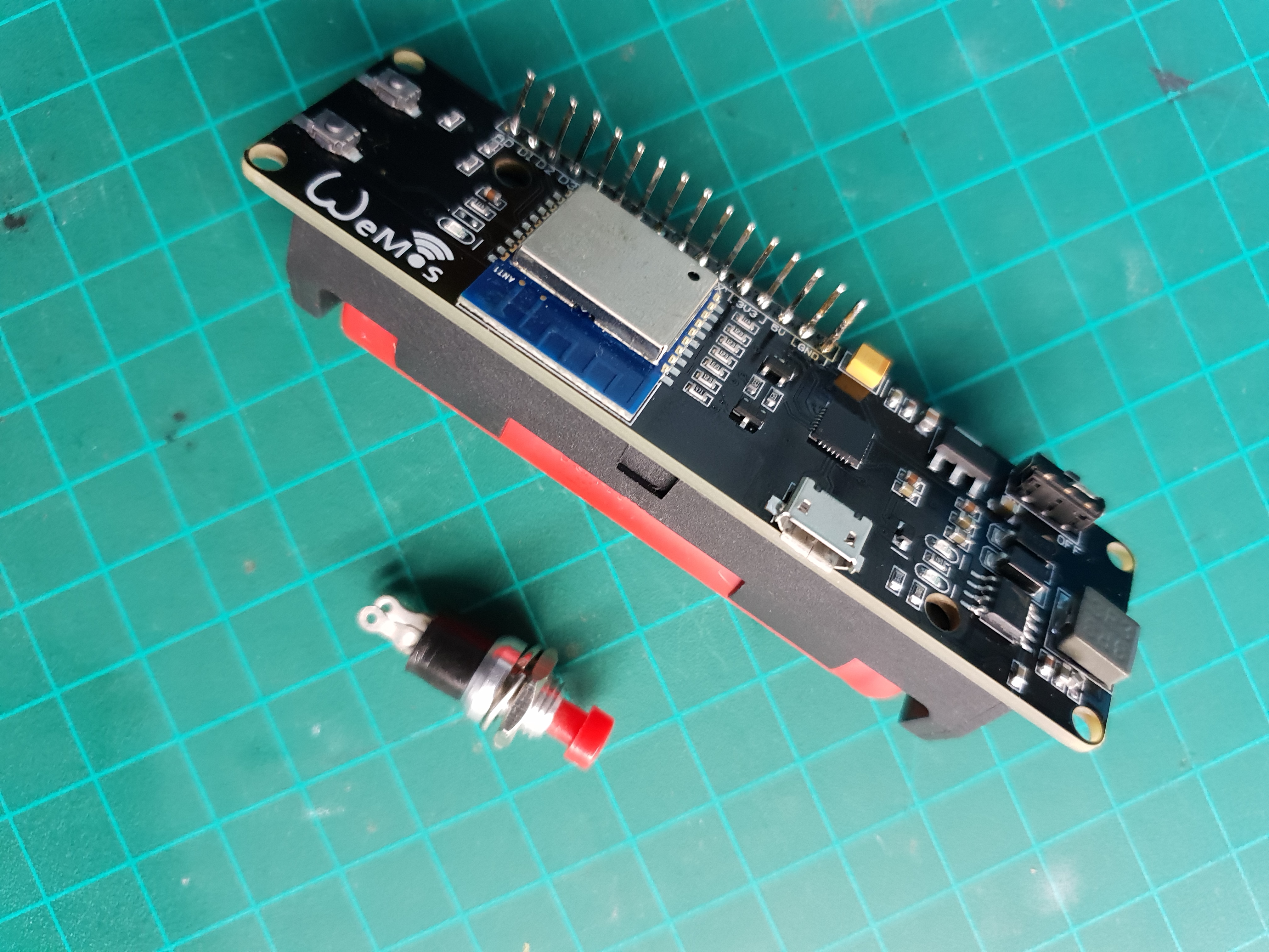
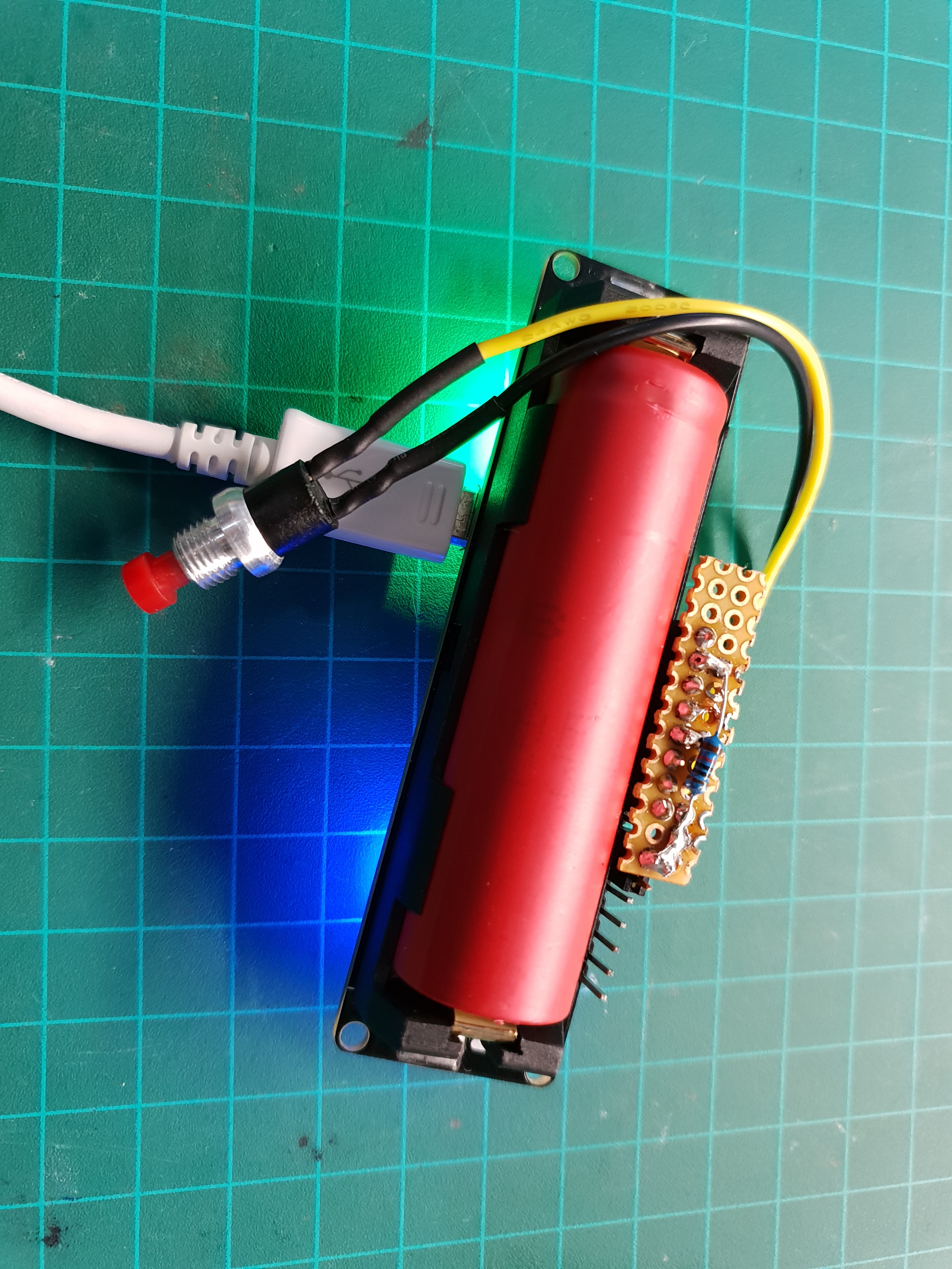
For ease of use and speeding up development, I used an ESP8266 module with built-in 18650 battery holder, charging circuit and FTDI that I usually use for prototyping.
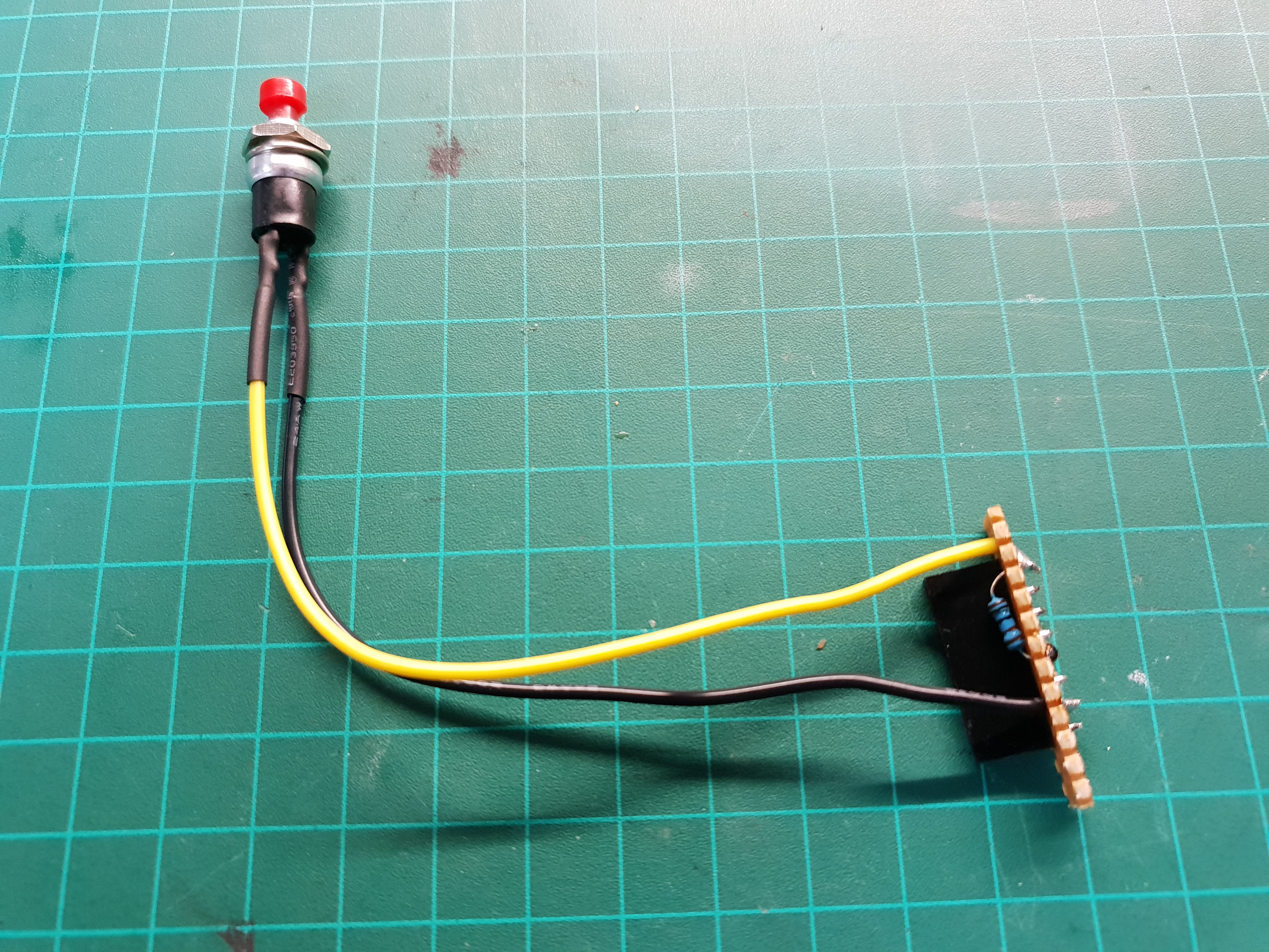
I added a small push button with a pull-down resistor on pin D6 and that’s it. pretty simple.
Case
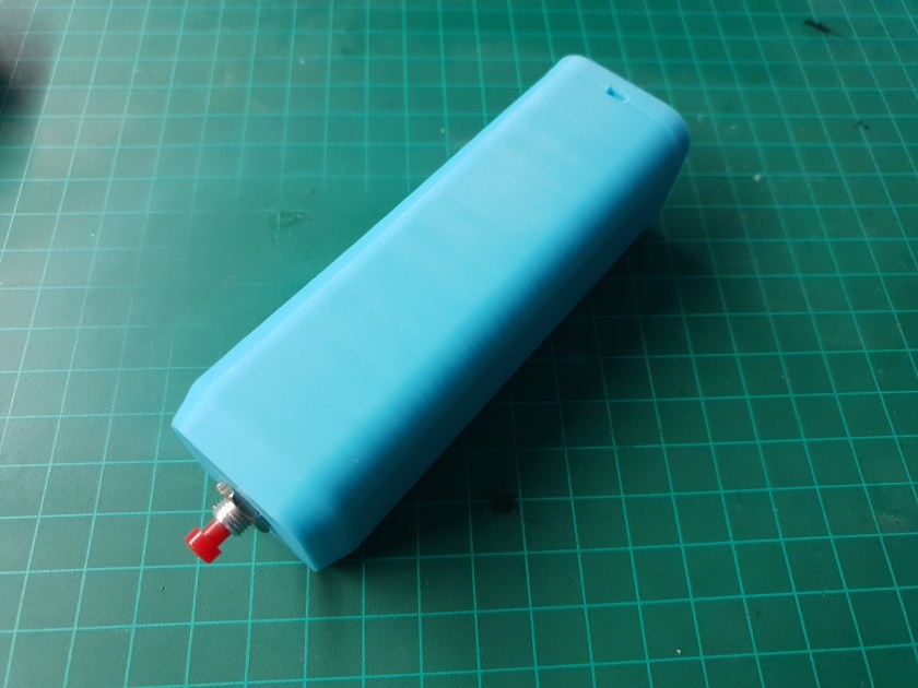
I wanted a case that can be designed very quickly and is not challenging to print because I expected the printing to be the most time consuming process.
The case is just a square tube with one side closed, a hole for the button and a friction fit bottom cap with notches for a screwdriver if it came out too tight. I threw some fillets for smoother printing and more comfortable fit in the hand.


Software
Speed is of the essence
I didn’t have time to R&D this thing and write efficient and clean code, so I took the code from a MQTT PIR sensor I’m working on and modified it to do the minimum I need.
The PIR sensor has digital output, so the input for the controller is basically identical to what I need to read the button. I only need to remove some extra PIR parts and disable some unneeded messages.
The code already has all the network and MQTT configured for my system.
Sleep?
One of the biggest challenges when working with batteries is reducing energy consumption, but for my application it’s not really a concern.
Usually, when you see a battery operated ESP8266, it’s a weather station or some other sensor that reports to the mothership every once in a while.
In that scenario, the timing isn’t important, a delay of 10 seconds in reporting time means nothing when a report is sent once an hour.
However, battery life is paramount. No one wants to replace batteries every week.
In my case, I need the device to work for a few hours and the most important thing for me was response time.
There are some controllers that support sleep mode with RF on that keep the connection to the network alive while the MCU sleeps. Unfortunately, the ESP8266 does not have a sleep mode with this feature. Even the lightest sleep mode disables radio.
This would not be a problem if reconnecting did not take 8 seconds on average. Some more configuration can lower the time to around 4 seconds, but this is still too much when you factor in the added delay of ~1-2 seconds that takes the rest of the system to process the message and execute the actions.
This lead me to abandon sleep altogether in this project. Let the microcontroller suck all the juice it wants while waiting for the button press. This results in ~1-2 seconds from button press to action executed and at most a day of battery life.
Having a replaceable 18650 battery instead of a soldered\welded battery that has to be charged also allowed me to quickly get the device working again if the battery runs out earlier than expected, making sleep mode even more unneeded.
Cleaning Up
I’m not going to publish the messy and savagely modified code from another project, So here’s a tested and working version based on the example from the PubSubClient arduino library.
#include <ESP8266WiFi.h>
#include "Adafruit_MQTT.h"
#include "Adafruit_MQTT_Client.h"

#define WLAN_SSID       "**********"           // Wi-Fi network name
#define WLAN_PASS       "**********"           // Wi-Fi password

#define AIO_SERVER      "**********"  // MQTT broker IP
#define AIO_SERVERPORT  1883             // MQTT broker port
#define AIO_USERNAME    "**********"           // MQTT username
#define AIO_KEY         "**********"           // MQTT password
#define AIO_CID         "emergency_button"     // MQTT client ID

int previousReading = LOW;

WiFiClient client;
Adafruit_MQTT_Client mqtt(&client, AIO_SERVER, AIO_SERVERPORT, AIO_USERNAME, AIO_KEY, AIO_CID);

Adafruit_MQTT_Publish status  = Adafruit_MQTT_Publish(&mqtt, AIO_CID "/911");
Adafruit_MQTT_Publish alarm_topic  = Adafruit_MQTT_Publish(&mqtt, AIO_CID "/911");

long lastMsg = 0;
char msg[50];
int value = 0;

int buttonPin = D6;
int ledPin = 16;


void MQTT_connect();

void setup_wifi() {

  delay(10);
  Serial.println();
  Serial.print("Connecting to ");
  Serial.println(WLAN_SSID);

  WiFi.begin(WLAN_SSID, WLAN_PASS);
  while (WiFi.status() != WL_CONNECTED) {
    delay(500);
    Serial.print(".");
  }

  Serial.println("");
  Serial.println("WiFi connected");
  Serial.println("IP address: ");
  Serial.println(WiFi.localIP());
}

void MQTT_connect() {
  int8_t ret;

  // Stop if already connected.
  if (mqtt.connected()) {
    return;
  }

  Serial.print("Connecting to MQTT... ");

  uint8_t retries = 3;
  while ((ret = mqtt.connect()) != 0) { // connect will return 0 for connected
       Serial.println(mqtt.connectErrorString(ret));
       Serial.println("Retrying MQTT connection in 5 seconds...");
       mqtt.disconnect();
       delay(5000);  // wait 5 seconds
       retries--;
       if (retries == 0) {
         // basically die and wait for WDT to reset me
         while (1);
       }
  }
  Serial.println("MQTT Connected!");
  status.publish("online");
}

void setup() {
  pinMode(BUILTIN_LED, OUTPUT);
  Serial.begin(115200);
  setup_wifi();
  pinMode(buttonPin, INPUT);
}

void loop() {
  MQTT_connect();

     if(digitalRead(buttonPin) == HIGH){
       if(previousReading == LOW){
         previousReading = HIGH;
         alarm_topic.publish("sos");
         Serial.print("button pressed");
         delay(50);
         }
       }

     if(digitalRead(buttonPin) == LOW){
        previousReading = LOW;
       }
}
I didn’t add it myself, but if anyone implements this, I suggest adding a voltage divider to measure the voltage of the battery and send another message when the battery is low. This would prevent frustration and allow you to replace the battery before it’s dead. This will also help you keep your batteries healthy if you don’t have an integrated battery protection circuit.
Backend
This button does not work alone, of course. I have a Raspberry Pi running Home Assistant (HA for short) and Mosquitto MQTT broker for home automation purposes.
(I won’t be explaining MQTT or HA in this article, you can find more information about them here and here respectively)
I created an automation in HA that triggers when the message from the button is received.
When the message is received, services are called to shut off the TV, turn on the light and send me a message to Telegram.
Here is the automation to be put in automations.yaml in HA:
- id: 'emergency_button'
  alias: code brown
  trigger:
  - platform: mqtt
    payload: 'sos'
    topic: emergency_button/911
  action:
  - service: telegram_bot.send_message
    data:
      message: CODE BROWN !
  - service: switch.turn_on
    data:
      entity_id: switch.cinema_light
  - service: switch.turn_off
    data:
      entity_id: switch.cinema_tv
Controlling the TV and lights is done with a Broadlink RM pro RF\IR bridge and the Broadlink component for HA.

The Telegram message is sent via the Telegram component for HA that controls a Telegram bot.

The files for the 3D printed case can be found on Thingiverse.
